Лейла Вавимен
3
Prompt
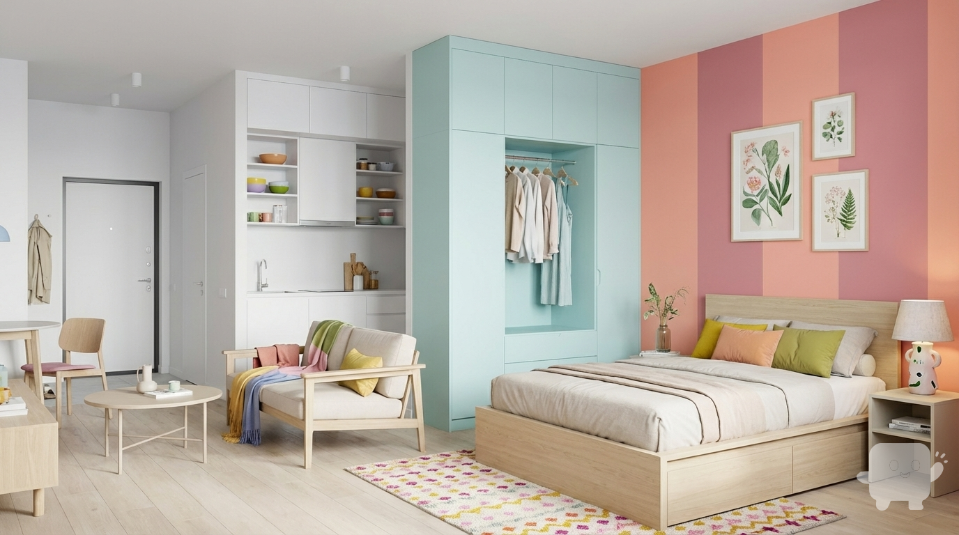
Design for a young woman without children, who is creating a space for herself. It's an uncluttered space, with almost all clothing in a large closet in the hallway (preferably, the closet should be in a very delicate mint-blue shade), and household items are hidden in the bed in the bedroom. The bed is a double bed, in neutral, natural shades of light wood. Bright accent colors + an accent wall in the bedroom. Maybe little bit of dopamine details
realisticstandard16:9
More like this
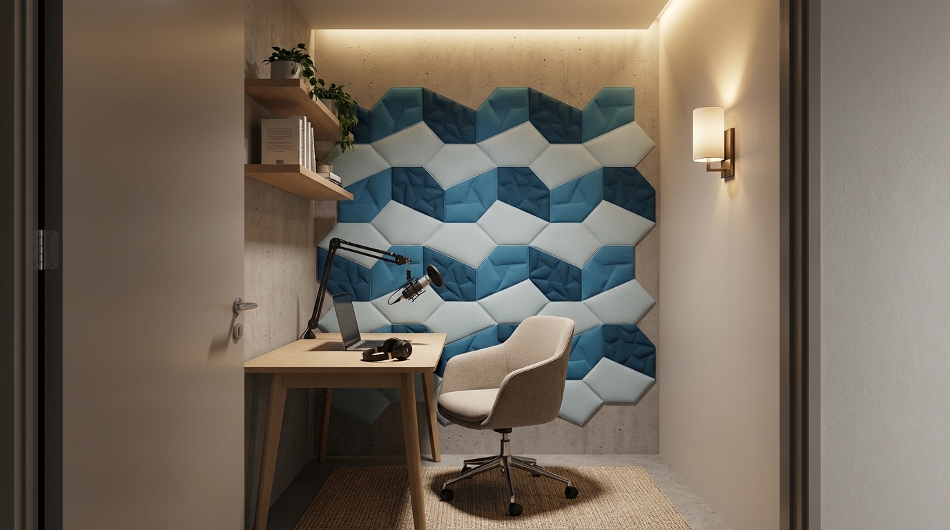
Compact focus room designed for video calls and podcasting, PET acoustic wall panels in soft muted colours behind the desk, small worktable with microphone, comfortable chair and simple shelves, warm ambient lighting with a wall sconce and hidden LED strip, cozy modern interior with matte finishes, no clutter, seen from the doorway at eye level, photorealistic architectural render, high detail, soft shadows, professional interior visualization quality, no people, no text, no logos.
Dec 4
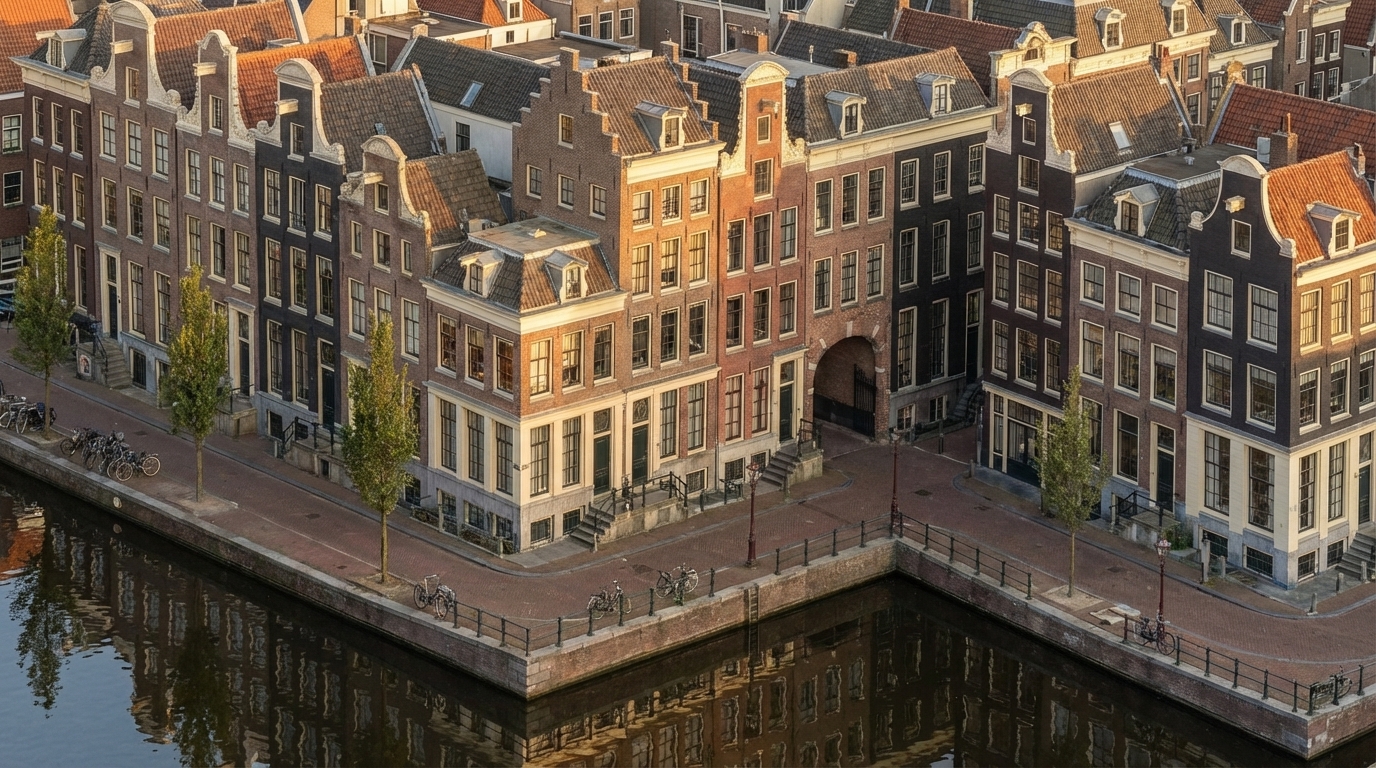
Convert this exact Revit massing into a fully detailed Amsterdam canal-house façade without changing any geometry. Keep the same isometric camera angle exactly as the original view. Apply seventeenth-century Dutch architectural style onto every block by dividing the long façade into narrow vertical bays inspired by real canal houses. Use authentic warm Dutch brick (brown, muted red, dark charcoal) with cream stone trim along corners, edges, and window frames. Add tall vertical windows with thin black mullions, and place stepped, bell, and neck gables only above the existing roof shapes. Convert all plain surfaces into rich brick textures, add cornices at massing offsets, and use recesses as historic alley-like details. Apply a subtle forward tilt (2–3°) to each bay visually, without editing the volumes.
Place a calm reflective canal in front of the full building length, with stone edges, metal railings, bikes, and slim Amsterdam street trees. Use warm golden-hour sunlight with soft reflections on windows and clear isometric reflections in the water. Render in ultra-photorealistic style with crisp textures, natural shadows, warm colors, HDR lighting, and slight filmic imperfections.
Negative prompt: no geometry edits, no modern curtain walls, no futuristic elements, no fisheye, no wrong gables, no unrealistic colors.
Dec 2
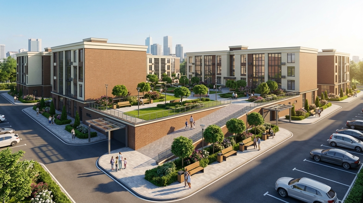
Render this residential complex exactly as designed, without altering its architecture, proportions, colors, façade materials, or geometry, including window sizes, shapes, and volumes.
Enhance the scene to be realistic, modern, and high-quality. Create a second-level courtyard located in the center of the residential complex, not outside the buildings. Include wide sidewalks, pedestrian walkways, benches, street lamps, trash bins, and decorative landscaping: green grass, neatly shaped trees, bushes, and flowerbeds, all matching the architectural style.
Add a ramp providing safe access to the second-level courtyard, integrated naturally with the buildings and landscaping. Include clean asphalt roads, organized parking spaces, several modern cars, and a realistic number of people — pedestrians, families, and residents — to create a lively atmosphere.
Add a subtle city skyline or urban background visible behind the complex, without distracting from the courtyard scene. Use soft daylight with realistic shadows and global illumination.
IMPORTANT: Place entrance ramps to the underground parking at the correct height — at the level of the first floor, elevated from the ground, exactly as in the original 3D model. Add modern metal-and-glass canopies above these ramps.
Ensure the final render is highly realistic, elegant, and visually cohesive, while preserving the exact form, geometry, and colors of the buildings.
Dec 2

Convert this exact Revit building massing into a complete and highly detailed Amsterdam-style architectural façade while strictly preserving every block, setback, height, and proportion of the original geometry. Apply the seventeenth-century Dutch canal house identity directly onto the existing horizontal mass, treating each vertical module, recess, and projection as an individual façade bay. Maintain the building as one continuous structure while visually subdividing it into rhythmically narrow Amsterdam-style segments with stepped, bell, and neck gables applied only above existing rooflines without altering the massing. Use warm brown, muted red, and deep charcoal brick textures combined with cream stone trim outlining corners and window surrounds. Integrate tall vertical windows with thin black mullions, placing decorative cornices at horizontal massing transitions and using recesses as historic alley moments. Convert all solid walls into richly detailed brick façades with traditional Dutch ornamentation, ensuring a subtle two-to-three-degree forward façade tilt for authenticity without modifying geometry.
Place a calm reflective canal directly along the entire front length of the building, adding stone edges, metal railings, bicycles, and slender street trees typical of Amsterdam’s canals. Illuminate the scene with warm golden-hour sunlight at a low angle, producing soft highlights on window glass and warm reflections in the canal. Use a wide-angle twenty-four to twenty-eight millimeter lens at eye level with a straight frontal perspective capturing clear water reflections and gentle ripples. Render the scene with ultra-photorealistic quality, high dynamic range, crisp material textures, natural shadow falloff, warm filmic color grading, and slight chromatic imperfections for historical realism.
Negative prompt: avoid geometry changes, futuristic elements, modern curtain walls, erased volumes, misaligned gables, unrealistic colors, and fisheye distortion. Ensure consistent weathering realistic brick aging subtle mortar variation historically accurate roof edges precise gable alignment natural ambient occlusion and refined reflective highlights across all surfaces for authenticity.
Dec 2
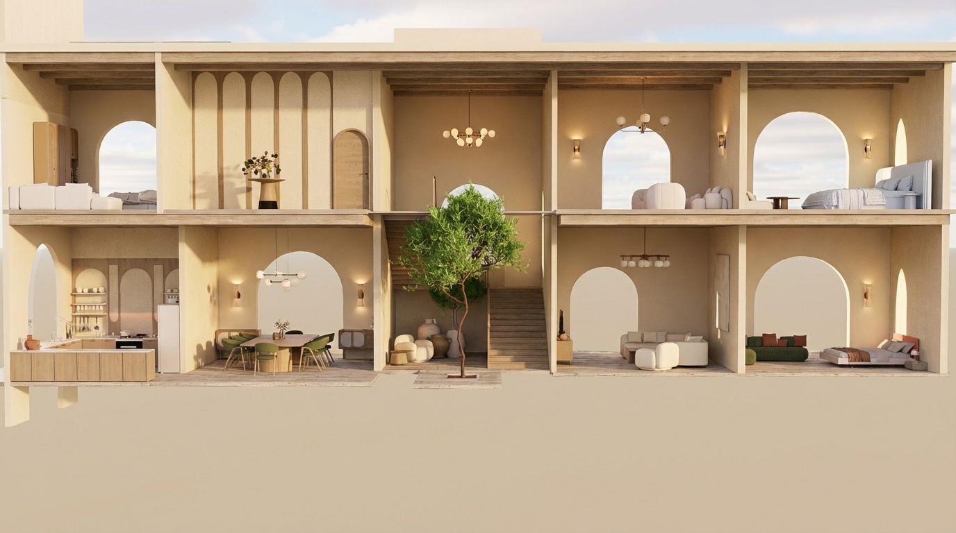
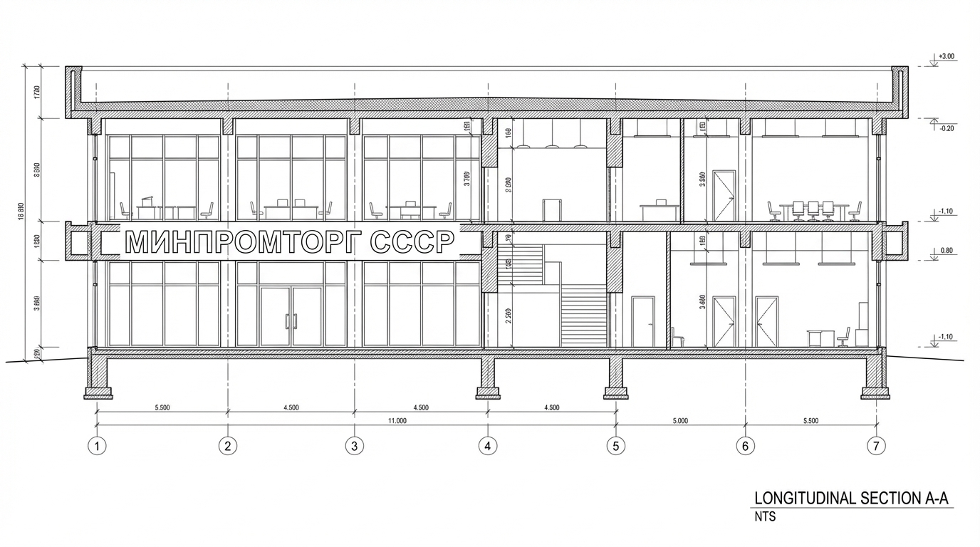
"Create an ultra-realistic render of this two-story Mediterranean-style villa section exactly as shown, keeping all room functions and all furniture placements unchanged.
All walls throughout both floors must be in beige tones only (warm Mediterranean beige).
GROUND FLOOR:
– Left side: open kitchen with upper and lower cabinets; dining area beside it.
– Middle: small seating area before the staircase; indoor vertical patio with a tree extending through both levels.
– Right side: main living room; and directly next to it a bedroom exactly as shown.
FIRST FLOOR:
– Left: bedroom; next to it a decorative gallery space with arched wall panels and a console table.
– Middle: double-height void above the indoor tree and staircase landing.
– Right: small sitting area; and at the far right a bedroom with arched opening.
Architectural requirements: preserve arches, openings, proportions, and room layout exactly as shown.
Rendering instructions:
– Do NOT change or modify any furniture; keep the exact furniture pieces and positions.
– All walls must be beige.
– Use modern lighting fixtures with warm Mediterranean ambiance.
– Use light-colored wood (not dark) for all wooden elements.
– Add highly detailed textures, refined materials, micro-details, realistic reflections, volumetric light, soft shadows, and a warm Mediterranean atmosphere.
– Maintain Mediterranean color palette: beige, warm brown, olive, deep burnt orange.
– Add elegant Mediterranean-style chandeliers without altering furniture layout
Dec 2

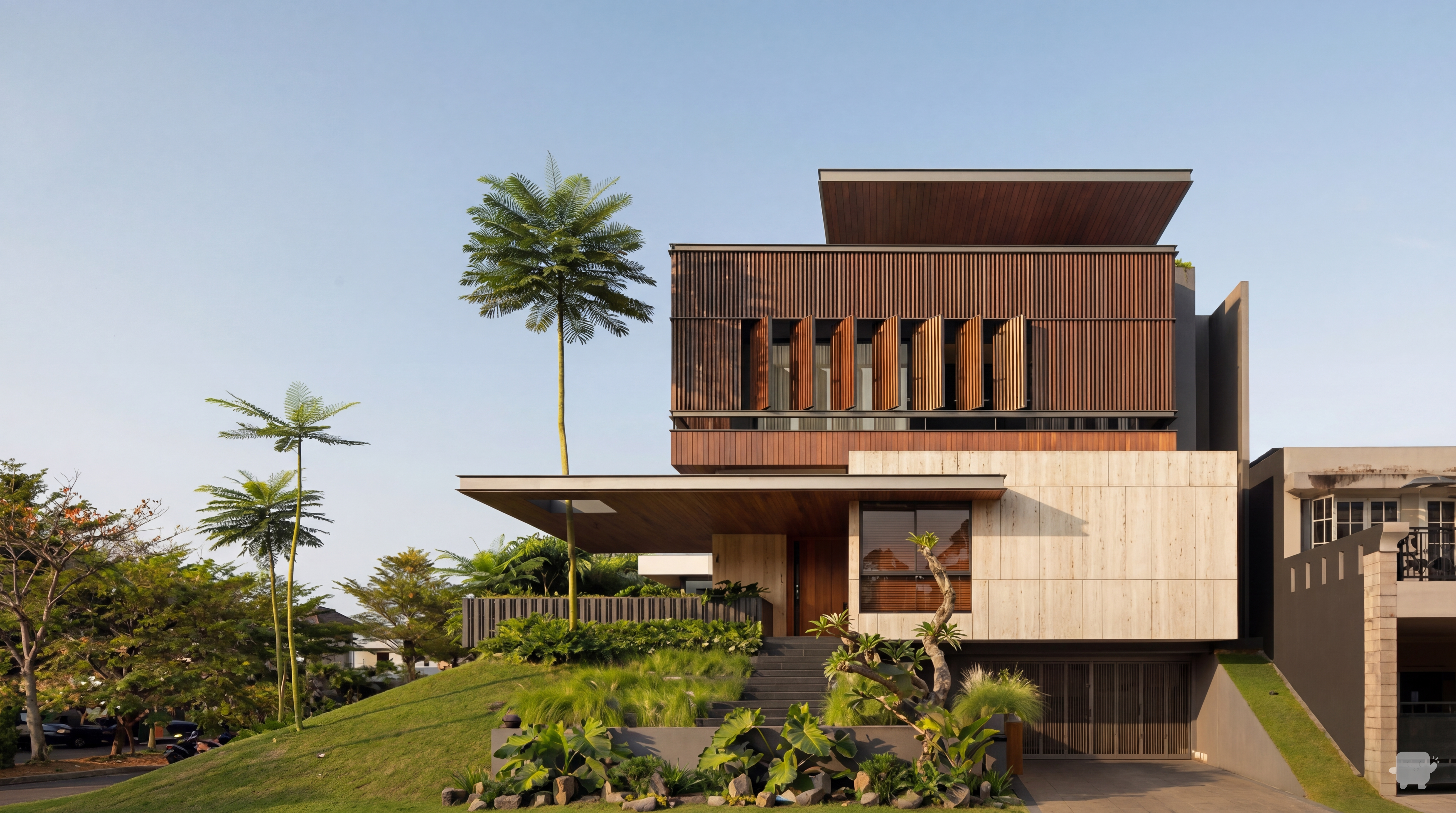
Create a super high-quality photorealistic exterior render of this modern villa from SketchUp/Revit. Preserve building geometry and camera angle. Apply realistic materials (stone, concrete, wood, glass) with accurate reflections. Use soft, natural, volumetric shadows, subtle global illumination, ambient daylight (without direct sun if desired), balanced exterior and interior lighting. Show interior details visible through windows, including chandelier and furniture. Include realistic landscaping and trees. Include subtle people for scale. No cars, no text, no stylization. Professional architectural visualization, cinematic and photorealistic
Dec 17
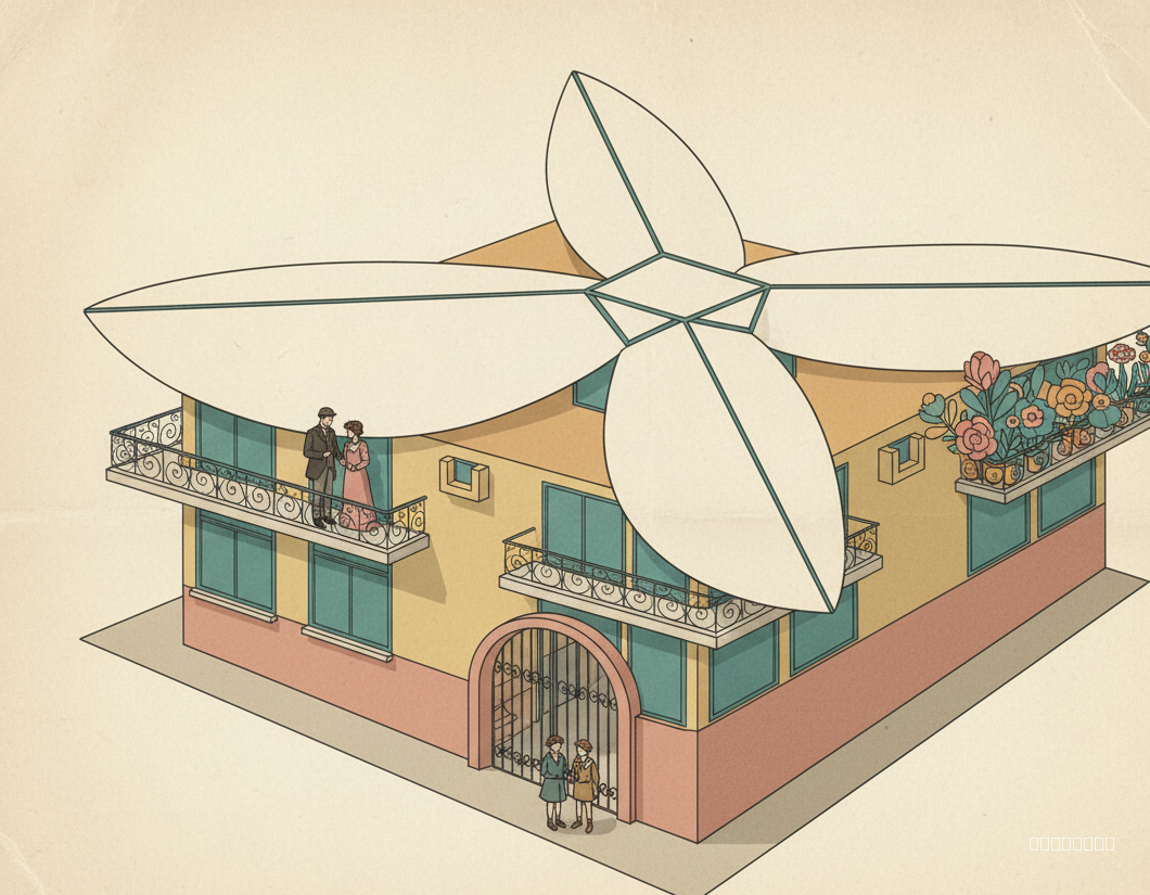
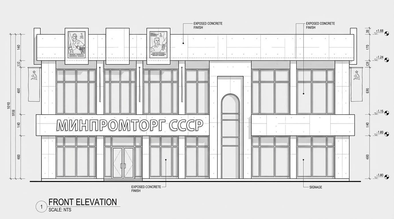
"Maintain original building proportions and design. Render a flat, 2D illustration in the style of vintage comics, using a limited palette of faded retro colors: muted teals, ochres, and rose pinks. Simulate the effect of aged paper. The building facade is a crisp white, like a cut-out piece of paper. Lighting should be soft and diffused, mimicking the glow of a vintage advertisement. Include six realistically rendered humans in early 20th-century European attire. A couple stands on a wrought-iron balcony, gazing outward. A woman tends to potted plants overflowing with vibrant, stylized blooms on another balcony. Two children, hand-in-hand, stand near the main gate at ground level. Plants should appear as distinct cutouts, adding to the collage effect. Emphasize texture and layering to create a vintage collage aesthetic."
Oct 6
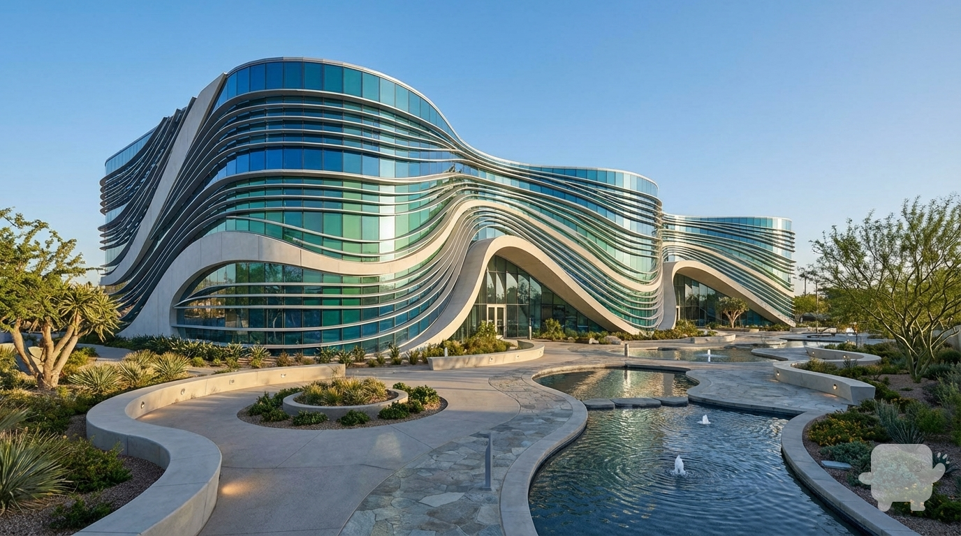
I am providing a basic 3D mass model of a building with no design details.
Please develop the architectural form based on a water wave concept, while keeping the original building massing intact.
I need smooth, fluid, dynamic façade lines inspired by the motion of water.
Requirements:
Create façade articulation inspired by water waves.
Add openings, shading elements, curves, or structural fins supporting the wave concept.
Use modern materials such as glass, aluminum, and GFRC.
Design a complete landscape for the site, including curved pathways, planting areas, ground lighting, and subtle water-themed elements.
Produce a high-quality final realistic render."
Dec 8
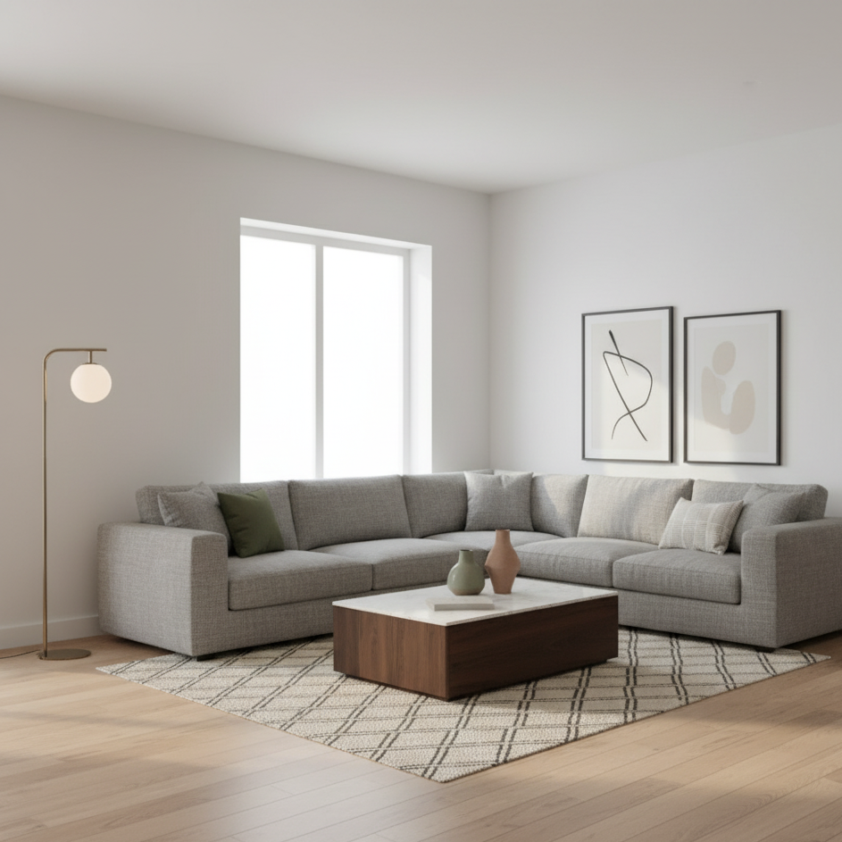
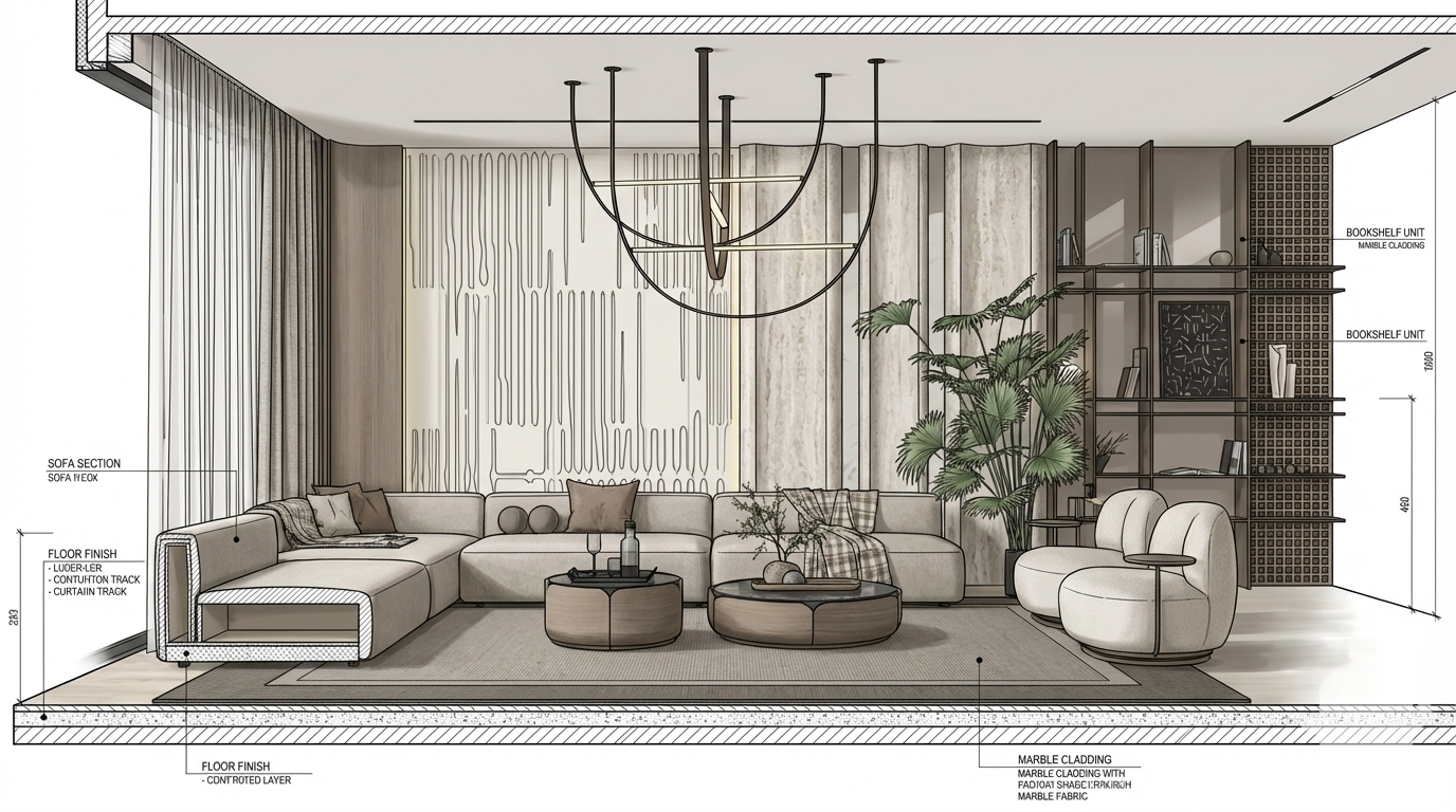
User Request: " Maintain aspect ratio and replicate floor/wall designs precisely. Based on the reference moodboard, furnish a modern living room. Walls are smooth, matte white plaster. Flooring is wide-plank, light oak hardwood with a subtle grain. Introduce a large, sectional sofa upholstered in textured grey linen. Add a low, rectangular coffee table of dark walnut with a honed marble top. Position a floor lamp with a brushed brass finish and a warm LED bulb behind the sofa. Natural light streams through a large window, casting soft shadows. Include a woven jute rug with a geometric pattern. Accessorize with ceramic vases in muted earth tones and abstract art on the walls. Overall, aim for a minimalist, sophisticated aesthetic with a focus on texture and natural materials."
Reference from @version 5:
- Original prompt: "add furniture"
- Style: realistic
- Quality: standard
- Aspect ratio: 16:9
- Image type: 3d-mass
- Processing time: 7s
Please generate a new image based on the user request, using the referenced version(s) as context. Maintain consistency with the referenced styles and settings where appropriate, but prioritize the user's specific request.
Oct 5
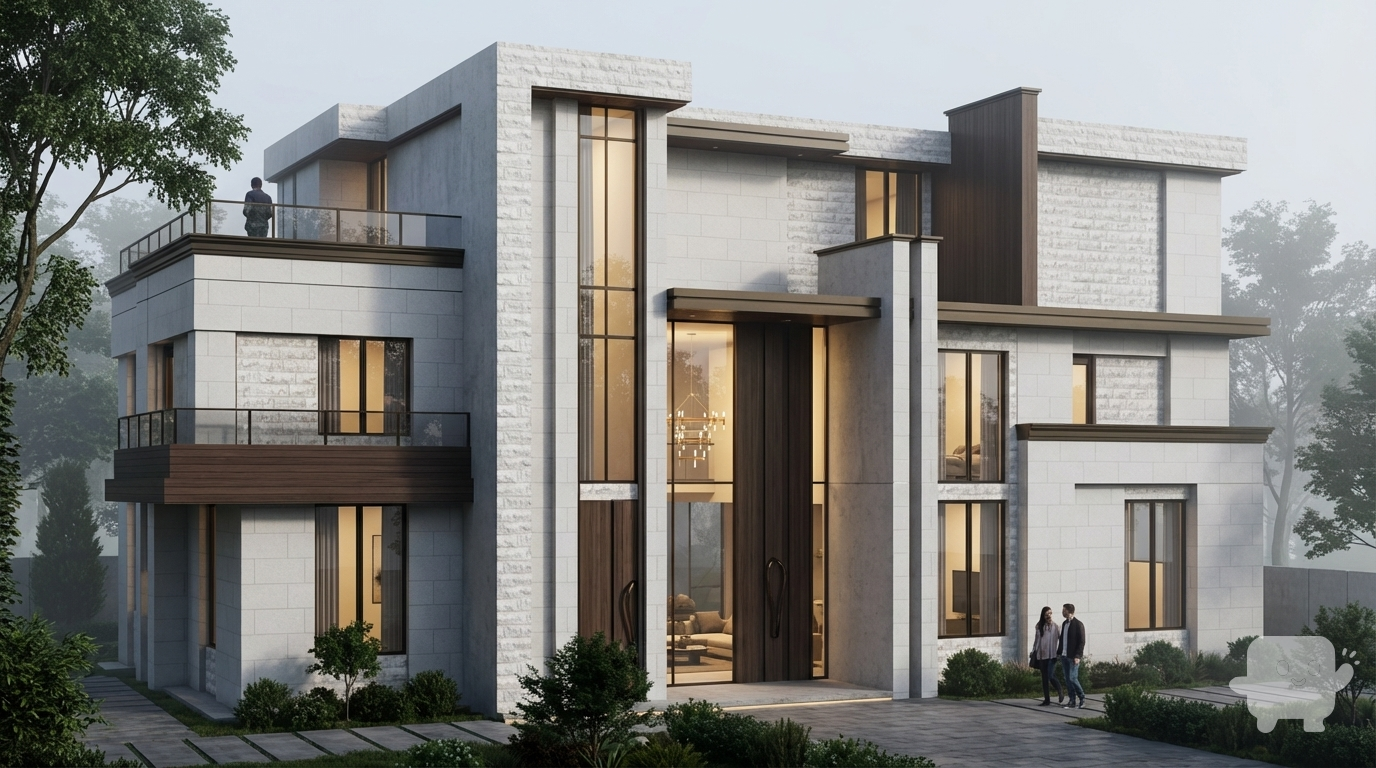
Create a super high-quality photorealistic exterior render of this modern villa from SketchUp/Revit. Preserve building geometry and camera angle. Apply realistic materials (stone, concrete, wood, glass) with accurate reflections. Use soft, natural, volumetric shadows, subtle global illumination, ambient daylight (without direct sun if desired), balanced exterior and interior lighting. Show interior details visible through windows, including chandelier and furniture. Include realistic landscaping and trees. Include subtle people for scale. No cars, no text, no stylization. Professional architectural visualization, cinematic and photorealistic
Dec 17
“Turn this architectural still image into a smooth cinematic animation. Keep the design, materials, colors, and proportions exactly the same. Add realistic daylight, subtle camera motion, natural shadows, and soft environmental effects. No distortion, no style change, no redesign — only a clean and realistic animation of the original image
Dec 8
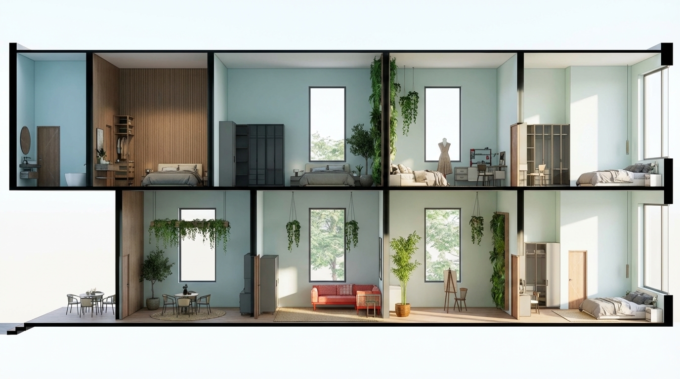
High-quality interior architectural section render, keeping all existing furniture exactly the same and in the same positions. Apply a soft biophilic design style with natural elements such as indoor plants, organic textures, and subtle greenery integration. Walls finished in a gentle breeze-color tone (light, airy, pastel cool-tone). Add clean, modern windows that enhance daylight penetration without altering the layout. Maintain the original spatial proportions, materials of furniture, and all architectural lines. Realistic lighting, soft natural light, high detail, photorealistic style, sharp linework, premium interior visualization, 4K
Dec 2