ayush
ayush
15Renders
6Likes
25Views
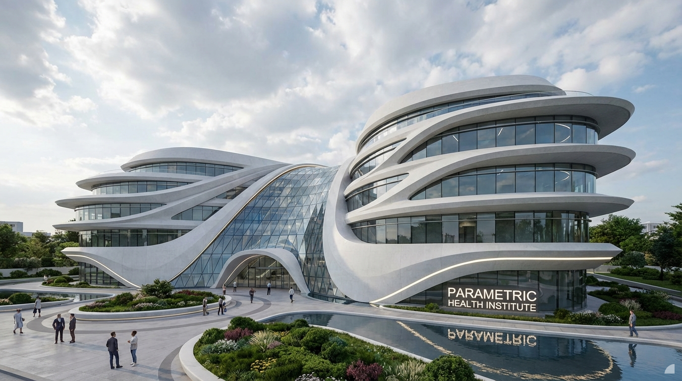
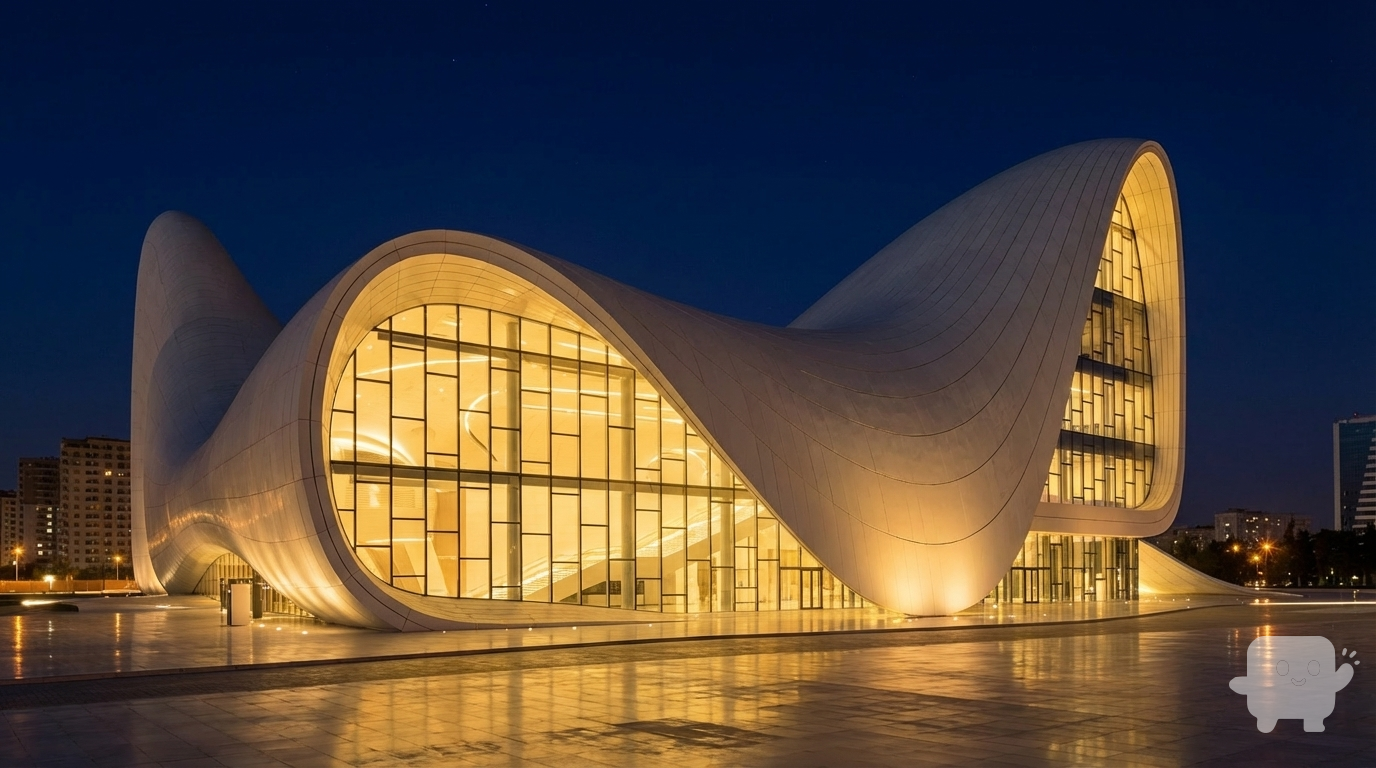
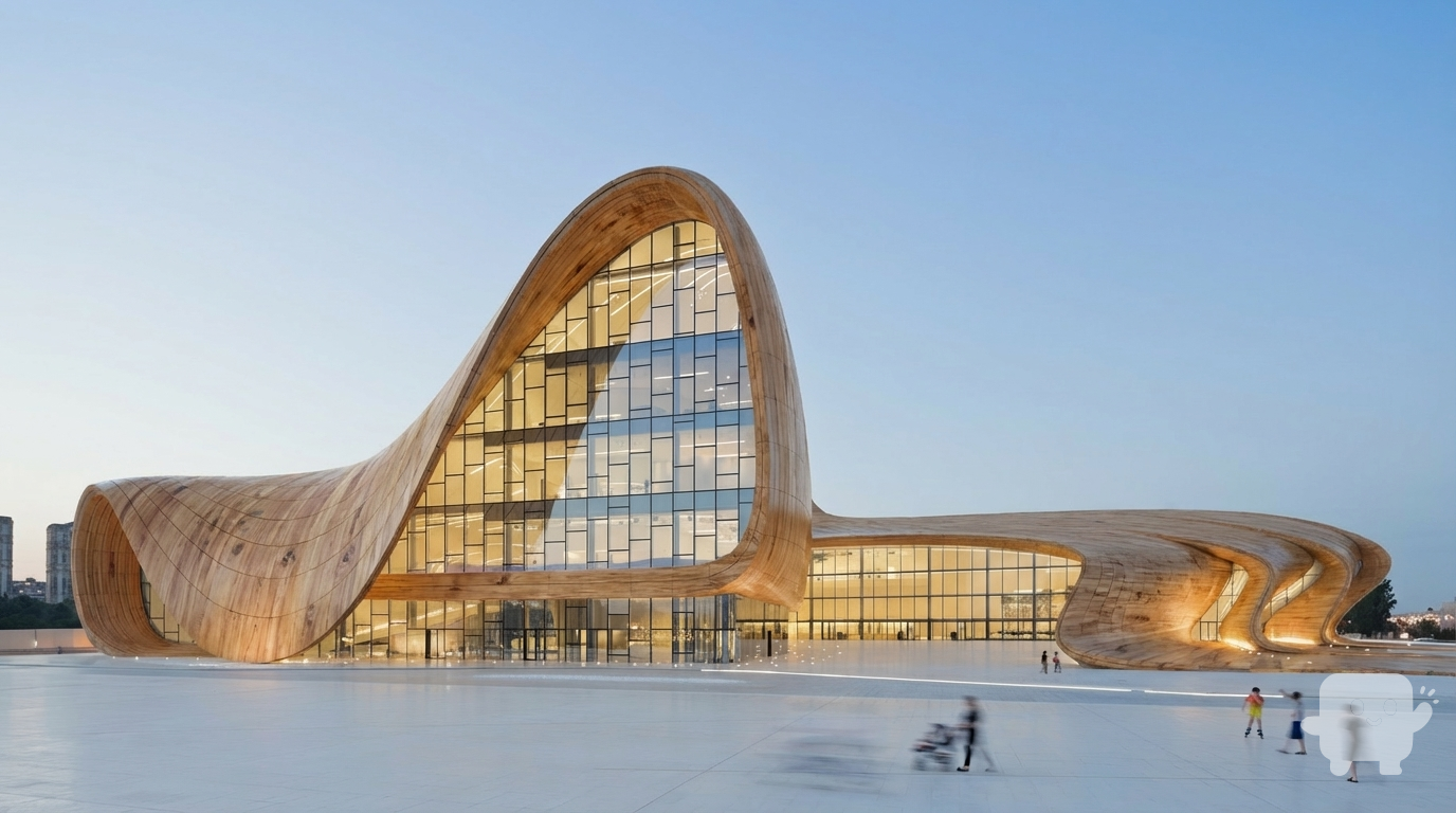
A photorealistic exterior architectural visualization of a futuristic hospital, distinctly in the parametric, fluid, curvilinear style reminiscent of Zaha Hadid Architects. The building features sweeping, organic forms with dynamic, undulating facades
Dec 19
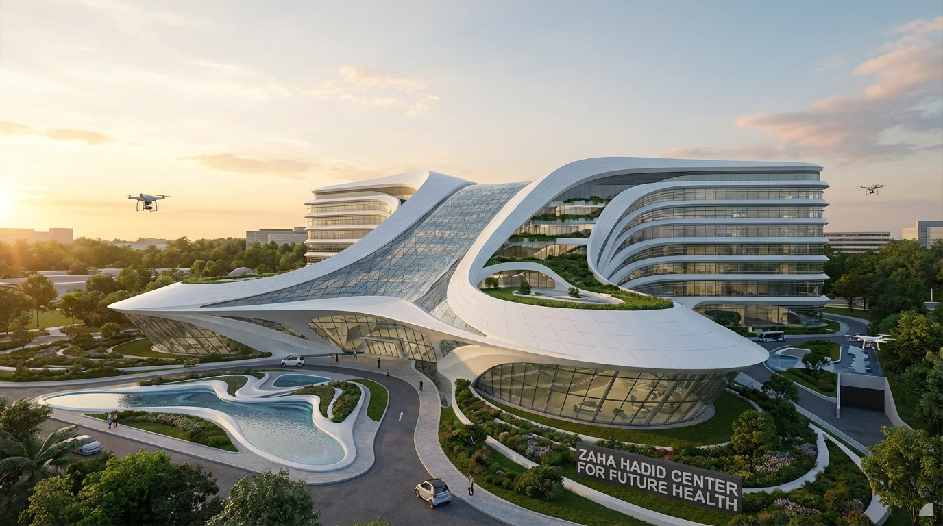
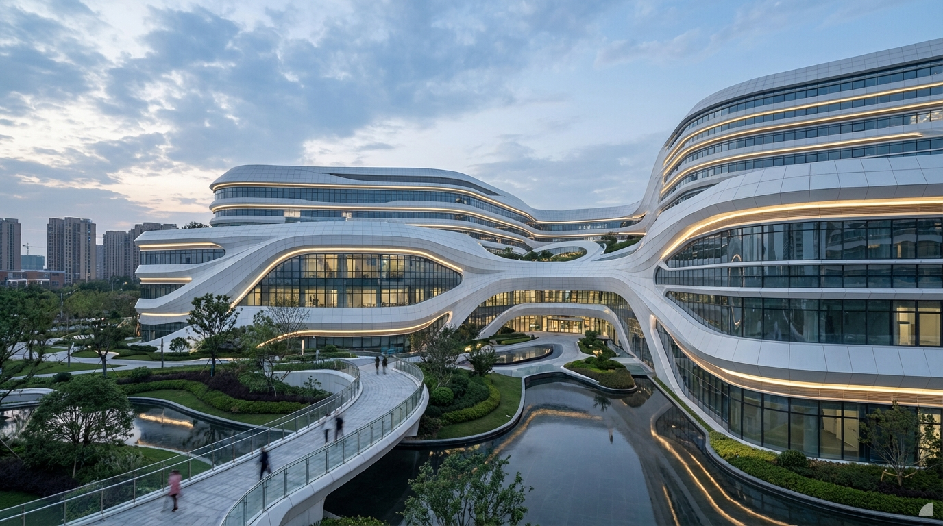
A photorealistic exterior architectural visualization of a futuristic hospital, distinctly in the parametric, fluid, curvilinear style reminiscent of Zaha Hadid Architects. The building features sweeping, organic forms with dynamic, undulating facades
Dec 19
Dec 12
Dec 12
Dec 11
A photorealistic exterior architectural visualization of a futuristic hospital, distinctly in the parametric, fluid, curvilinear style reminiscent of Zaha Hadid Architects. The building features sweeping, organic forms with dynamic, undulating facades
Dec 19
Dec 12
Dec 12
Dec 12
Dec 11
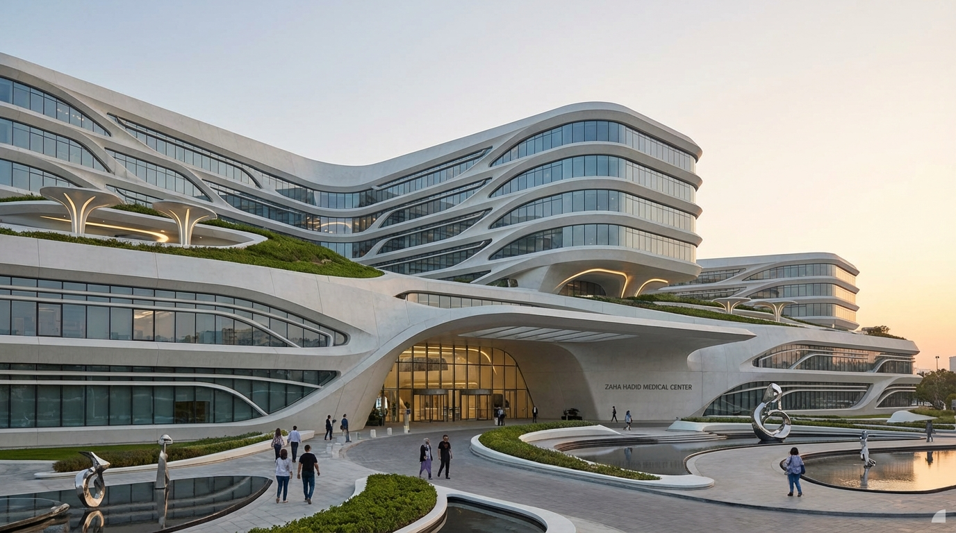
A photorealistic exterior architectural visualization of a futuristic hospital, distinctly in the parametric, fluid, curvilinear style reminiscent of Zaha Hadid Architects. The building features sweeping, organic forms with dynamic, undulating facades
Dec 19
Dec 12
Dec 12
Dec 11
Dec 11
You've reached the end