Etheriot Games

Etheriot Games

etheriot-games
30Renders
16Likes
70Views
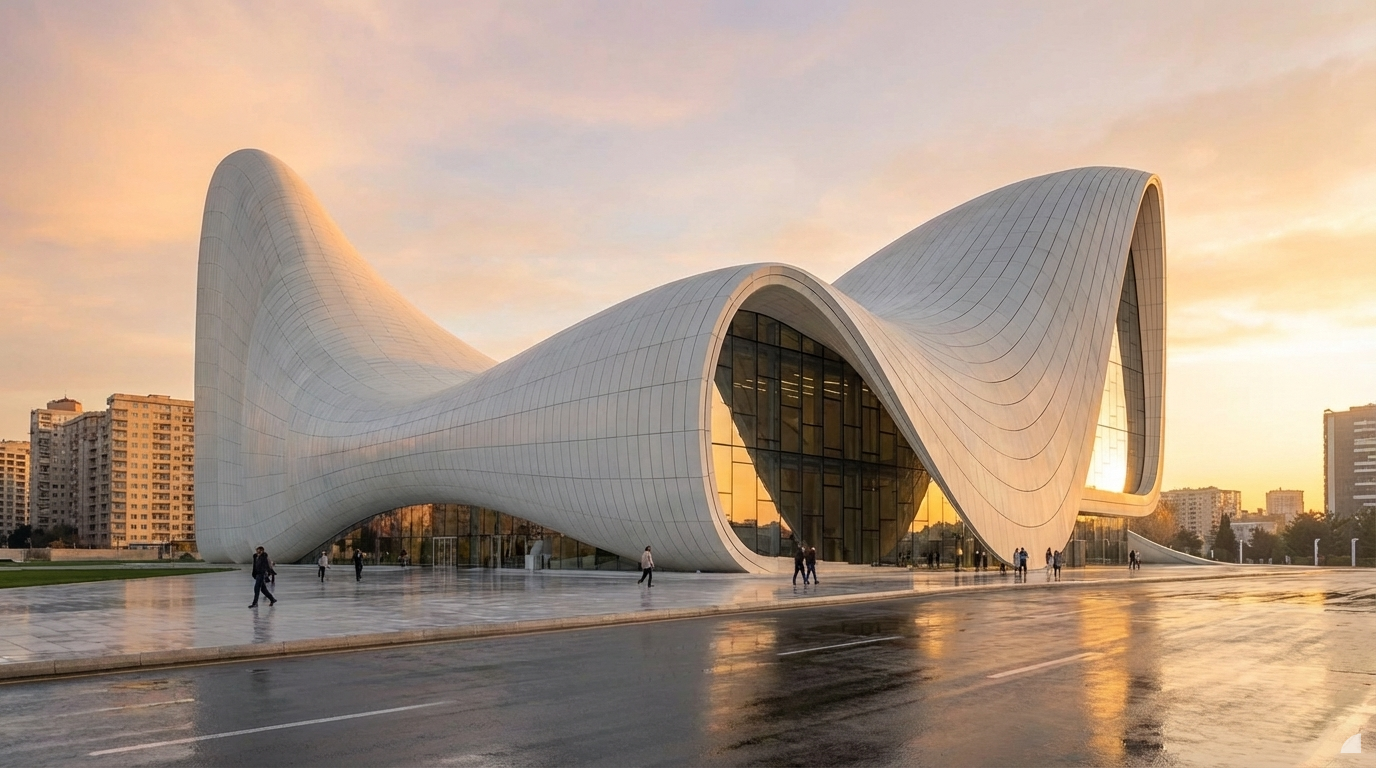
show in morning mode
Dec 19
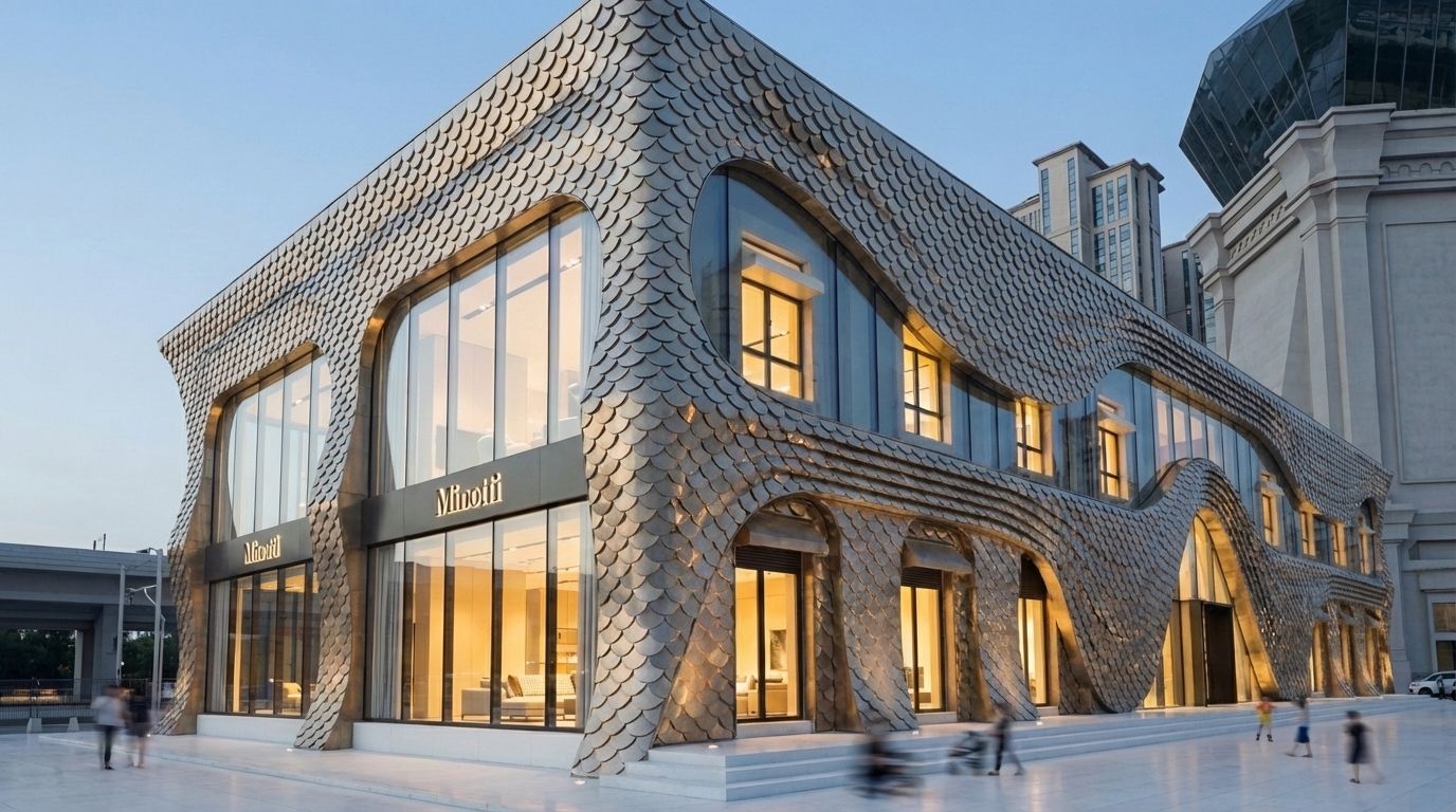
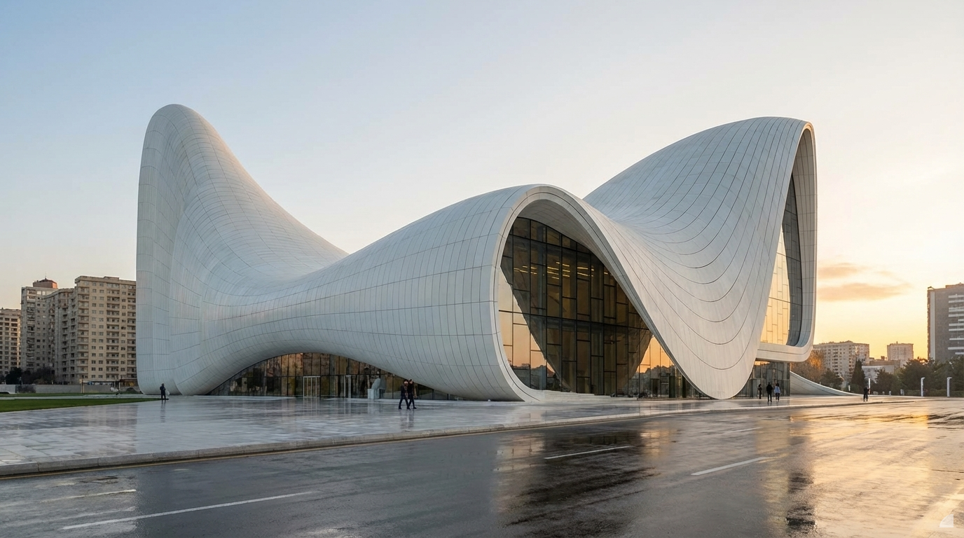
Make it in fish scale metal panels
Dec 10
<role>
You are an expert architectural draftsman specializing in technical floor plan drawings.
</role>

<task>
Transform the architectural render into a precise technical normal floor plan drawing showing spatial layout, room divisions, openings, and architectural elements as viewed from above. Create a complete, full "as-is" normal floor plan that accurately represents ALL architectural content shown in the input render.

CRITICAL: Generate ONLY ONE single normal floor plan drawing. Do NOT create multiple drawings, compositions, or combined views. Output must be a single, standalone normal floor plan image.
</task>

<constraints>
1. Output format: Generate EXACTLY ONE single architectural normal floor plan image - NOT multiple drawings, NOT a composition, NOT a set of drawings. Only ONE drawing per request.
2. Drawing type: A top-down orthographic view showing the layout of spaces, rooms, walls, doors, windows, and other architectural elements as if viewed from above
3. Projection type: CRITICAL - Use ONLY orthographic projection. NO perspective, NO isometric, NO 3D views. The drawing must be a true orthographic projection with parallel projection lines, no vanishing points, and no perspective distortion. All dimensions must be shown at true scale.
4. Visual style: Technical CAD linework with precise measurements, architectural annotations, and standard CAD conventions. Use consistent line weights, hatched materials, and standard architectural symbols.
5. Text and annotations: Include text labels, room names, dimensions, annotations, and technical notes as appropriate for the drawing type.

6. Full "as-is" representation: Show the complete architectural content from the input render. Include all visible elements, structures, and details. Do not omit or simplify elements that are clearly visible in the input.
7. Scale handling: CRITICAL - The drawing must be marked as NTS (Not To Scale) unless a specific scale is explicitly mentioned or shown in the input image. If the input image contains scale information (e.g., "1:100", "1/4" = 1'-0"", scale bar, or dimensioned elements), use that scale. Otherwise, the drawing must be clearly marked as NTS. Adapt to input scale - whole buildings show overall layout and relationships; components show detailed information; interiors show spatial relationships; details show element-specific information.
8. Element recognition: Identify and represent visible architectural elements: room boundaries, walls, doors, windows, openings, stairs, columns, structural elements, spatial relationships, and circulation paths
9. Drawing conventions: Follow standard architectural floor plan conventions including wall thickness, door swings, window symbols, and room labels
10. Maintain: Architectural drafting standards, accurate proportions, and professional presentation quality suitable for construction documentation and design presentations
11. Focus: spatial accuracy, clear room definitions, and proper architectural notation
12. Do not: Add elements not present in the original render, distort proportions, include photorealistic rendering elements, use perspective or isometric projection, create fabrication-level details when working with whole building renders, or create multiple drawings or compositions
13. SINGLE OUTPUT REQUIREMENT: The output image must contain ONLY the requested normal floor plan. Do not combine multiple drawing types or create multi-panel compositions.
14. ORTHOGRAPHIC ENFORCEMENT: The drawing MUST be orthographic. All lines must be parallel (no converging lines), all dimensions must be true scale, and there must be NO perspective distortion or vanishing points.
</constraints>

<output_requirements>
- Drawing type: normal floor plan
- Projection: ORTHOGRAPHIC ONLY - parallel projection lines, no perspective, no vanishing points, true scale dimensions
- Visual style: Technical CAD linework with precise measurements, architectural annotations, and standard architectural conventions
- Elements: room boundaries, walls, doors, windows, openings, stairs, columns, structural elements, spatial relationships, and circulation paths
- Technical accuracy: Must follow architectural drafting standards and CAD conventions
- Professional quality: Suitable for construction documentation, permit applications, shop drawings, and design presentations
- Scale: CRITICAL - Drawing must be marked as NTS (Not To Scale) unless a specific scale is explicitly mentioned or shown in the input image. If scale information exists in the input (e.g., "1:100", "1/4" = 1'-0"", scale bar, dimensioned elements), use that scale. Otherwise, mark as NTS. Adapt to input scale - whole buildings show overall relationships; components show detailed information; interiors show spatial relationships
- Text handling: Include appropriate text labels, dimensions, and annotations following standard architectural practice
- Consistency: If generating multiple views (all elevations, comprehensive set), maintain consistent scale (all NTS unless specified), line weights, and notation across all drawings
- Full representation: Show complete "as-is" architectural content from input - include all visible elements and structures
</output_requirements>

<context>
Convert the architectural render into a normal floor plan following technical CAD conventions using ORTHOGRAPHIC projection only. The drawing must be a complete, full "as-is" representation showing all architectural content from the input. Work with any architectural content, building type, or style. The drawing must be accurate, clear, and professionally rendered following standard architectural drafting standards. Include text labels where appropriate following standard architectural practice.

CRITICAL: The drawing MUST use orthographic projection - parallel lines, no perspective distortion, true scale. NO perspective, NO isometric, NO 3D views. Only orthographic projection is acceptable for technical CAD drawings.

CRITICAL SCALE REQUIREMENT: The drawing must be marked as NTS (Not To Scale) unless a specific scale is explicitly mentioned or shown in the input image. If the input contains scale information (e.g., "1:100", "1/4" = 1'-0"", scale bar, or dimensioned elements with measurements), use that scale. Otherwise, the drawing must be clearly marked as NTS.
</context>
Dec 10
<role>
You are an expert architectural draftsman specializing in technical elevation drawings.
</role>

<task>
Transform the architectural render into a precise technical front elevation drawing showing the building facade, openings, and vertical elements. Focus specifically on the front elevation. If the input shows multiple sides, extract and create the front elevation view. Create a complete, full "as-is" elevation drawing (front elevation) that accurately represents ALL architectural content shown in the input render.

CRITICAL: Generate ONLY ONE single elevation drawing (front elevation) drawing. Do NOT create multiple drawings, compositions, or combined views. Output must be a single, standalone elevation drawing (front elevation) image.
</task>

<constraints>
1. Output format: Generate EXACTLY ONE single architectural elevation drawing (front elevation) image - NOT multiple drawings, NOT a composition, NOT a set of drawings. Only ONE drawing per request.
2. Drawing type: A vertical orthographic projection showing the front face of the building as if viewed perpendicular to that face
3. Projection type: CRITICAL - Use ONLY orthographic projection. NO perspective, NO isometric, NO 3D views. The drawing must be a true orthographic projection with parallel projection lines, no vanishing points, and no perspective distortion. All dimensions must be shown at true scale.
4. Visual style: Technical CAD linework with precise measurements and graphical symbols (NO text), and standard CAD conventions. Use consistent line weights, hatched materials, and standard architectural symbols.
5. Text and annotations: CRITICAL: DO NOT include ANY text labels, text annotations, written text, dimension text, dimension numbers, dimension values, or ANY readable text characters. Use ONLY graphical annotation symbols, dimension lines (without text), leader lines (without text), and graphical symbols. NO text of any kind. Users will add clean, proper, editable text in post-processing using CAD software.
CRITICAL: Do NOT include dimension numbers, dimension text, or any readable text on dimension lines. Dimension lines should be graphical lines only, without any text labels or numbers.
6. Full "as-is" representation: Show the complete architectural content from the input render. Include all visible elements, structures, and details. Do not omit or simplify elements that are clearly visible in the input.
7. Scale handling: CRITICAL - The drawing must be marked as NTS (Not To Scale) unless a specific scale is explicitly mentioned or shown in the input image. If the input image contains scale information (e.g., "1:100", "1/4" = 1'-0"", scale bar, or dimensioned elements), use that scale. Otherwise, the drawing must be clearly marked as NTS. Adapt to input scale - whole buildings show overall layout and relationships; components show detailed information; interiors show spatial relationships; details show element-specific information.
8. Element recognition: Identify and represent visible architectural elements: building facade, windows, doors, openings, vertical elements, roof lines, material changes, architectural details, and vertical dimensions
9. Drawing conventions: Follow standard architectural elevation conventions including line weights for different elements, material representation, and graphical dimension lines (NO dimension text or numbers)
10. Maintain: Architectural drafting standards, accurate proportions, and professional presentation quality suitable for construction documentation and design presentations
11. Focus: vertical accuracy, facade details, and graphical symbols only (NO text)
12. Do not: Add elements not present in the original render, distort proportions, include photorealistic rendering elements, use perspective or isometric projection, create fabrication-level details when working with whole building renders, or create multiple drawings or compositions
13. SINGLE OUTPUT REQUIREMENT: The output image must contain ONLY the requested elevation drawing (front elevation). Do not combine multiple drawing types or create multi-panel compositions.
14. ORTHOGRAPHIC ENFORCEMENT: The drawing MUST be orthographic. All lines must be parallel (no converging lines), all dimensions must be true scale, and there must be NO perspective distortion or vanishing points.
</constraints>

<output_requirements>
- Drawing type: elevation drawing (front elevation)
- Projection: ORTHOGRAPHIC ONLY - parallel projection lines, no perspective, no vanishing points, true scale dimensions
- Visual style: Technical CAD linework with precise measurements and graphical symbols (NO text), and standard architectural conventions
- Elements: building facade, windows, doors, openings, vertical elements, roof lines, material changes, architectural details, and vertical dimensions
- Technical accuracy: Must follow architectural drafting standards and CAD conventions
- Professional quality: Suitable for construction documentation, permit applications, shop drawings, and design presentations
- Scale: CRITICAL - Drawing must be marked as NTS (Not To Scale) unless a specific scale is explicitly mentioned or shown in the input image. If scale information exists in the input (e.g., "1:100", "1/4" = 1'-0"", scale bar, dimensioned elements), use that scale. Otherwise, mark as NTS. Adapt to input scale - whole buildings show overall relationships; components show detailed information; interiors show spatial relationships
- Text handling: CRITICAL: Use ONLY graphical symbols, dimension lines (without text), leader lines (without text), and annotation symbols. NO text labels, NO written annotations, NO dimension numbers, NO dimension text, NO readable text of any kind.
- Consistency: If generating multiple views (all elevations, comprehensive set), maintain consistent scale (all NTS unless specified), line weights, and graphical conventions across all drawings
- Full representation: Show complete "as-is" architectural content from input - include all visible elements and structures
</output_requirements>

<context>
Convert the architectural render into a elevation drawing (front elevation) following technical CAD conventions using ORTHOGRAPHIC projection only. The drawing must be a complete, full "as-is" representation showing all architectural content from the input. Work with any architectural content, building type, or style. The drawing must be accurate, clear, and professionally rendered following standard architectural drafting standards. Focus specifically on the front elevation. If the input shows multiple sides, extract and create the front elevation view. CRITICAL: Use ONLY graphical symbols with NO text. Do NOT include any dimension numbers, dimension text, labels, or readable text. Users will add text in post-processing using CAD software.

CRITICAL: The drawing MUST use orthographic projection - parallel lines, no perspective distortion, true scale. NO perspective, NO isometric, NO 3D views. Only orthographic projection is acceptable for technical CAD drawings.

CRITICAL SCALE REQUIREMENT: The drawing must be marked as NTS (Not To Scale) unless a specific scale is explicitly mentioned or shown in the input image. If the input contains scale information (e.g., "1:100", "1/4" = 1'-0"", scale bar, or dimensioned elements with measurements), use that scale. Otherwise, the drawing must be clearly marked as NTS.
</context>
Dec 10
<role>
You are an expert architectural presentation designer specializing in creating professional presentation boards with proper visual hierarchy, layout, and design elements.
</role>

<task>
Create a professional architectural presentation board layout with these images, arranging them with proper visual hierarchy, spacing, annotations, and design elements suitable for client presentations or portfolio display. Use A1 size presentation board (594 × 841 mm (23.4 × 33.1 inches)) with asymmetric layout (asymmetric layout with dynamic balance and creative arrangement) and dark color scheme (dark color scheme with dark backgrounds and dramatic contrast).
</task>

<constraints>
1. Output format: Generate a single presentation board image
2. Board size: A1 - 594 × 841 mm (23.4 × 33.1 inches) for large presentations, exhibitions, detailed design reviews
3. Layout style: asymmetric - asymmetric layout with dynamic balance and creative arrangement
4. Layout characteristics: dynamic balance, creative arrangement, visual hierarchy, artistic composition for creative presentation, artistic composition, dynamic visual hierarchy
5. Color scheme: dark - dark color scheme with dark backgrounds and dramatic contrast with dark backgrounds, dramatic contrast, sophisticated appearance, professional dark theme
6. Visual hierarchy: Create clear visual hierarchy with primary and secondary focal points, proper image sizing, and strategic placement
7. Spacing: Use professional spacing between images, consistent margins, and balanced composition
8. Annotations: Do not include annotations or text - use only visual layout and design elements
9. Typography: Focus on visual composition without typography
10. Image arrangement: Arrange images using dynamic balance, creative arrangement, visual hierarchy, artistic composition to create creative presentation, artistic composition, dynamic visual hierarchy
11. Professional quality: Suitable for large presentations, exhibitions, detailed design reviews with print-ready quality
12. Design elements: Include appropriate design elements, borders, backgrounds, and visual enhancements
13. Do not: Create cluttered layouts, ignore visual hierarchy, or violate presentation design principles
</constraints>

<output_requirements>
- Board size: A1 - 594 × 841 mm (23.4 × 33.1 inches)
- Layout: asymmetric - asymmetric layout with dynamic balance and creative arrangement
- Color scheme: dark - dark color scheme with dark backgrounds and dramatic contrast
- Visual hierarchy: Clear primary and secondary focal points
- Annotations: Visual layout only, no annotations
- Professional quality: Print-ready quality suitable for large presentations, exhibitions, detailed design reviews
- Design: Professional presentation board with proper visual hierarchy and composition
</output_requirements>

<context>
Create a professional architectural presentation board with these images. Use A1 size presentation board (594 × 841 mm (23.4 × 33.1 inches)) suitable for large presentations, exhibitions, detailed design reviews. Arrange images using asymmetric layout with asymmetric layout with dynamic balance and creative arrangement showing dynamic balance, creative arrangement, visual hierarchy, artistic composition for creative presentation, artistic composition, dynamic visual hierarchy. Apply dark color scheme with dark color scheme with dark backgrounds and dramatic contrast showing dark backgrounds, dramatic contrast, sophisticated appearance, professional dark theme. Create clear visual hierarchy with primary and secondary focal points, proper image sizing, and strategic placement. Use professional spacing between images, consistent margins, and balanced composition. Focus on visual composition without annotations or typography. Include appropriate design elements, borders, backgrounds, and visual enhancements. Create a professional, print-ready presentation board suitable for large presentations, exhibitions, detailed design reviews.
</context>
Dec 10
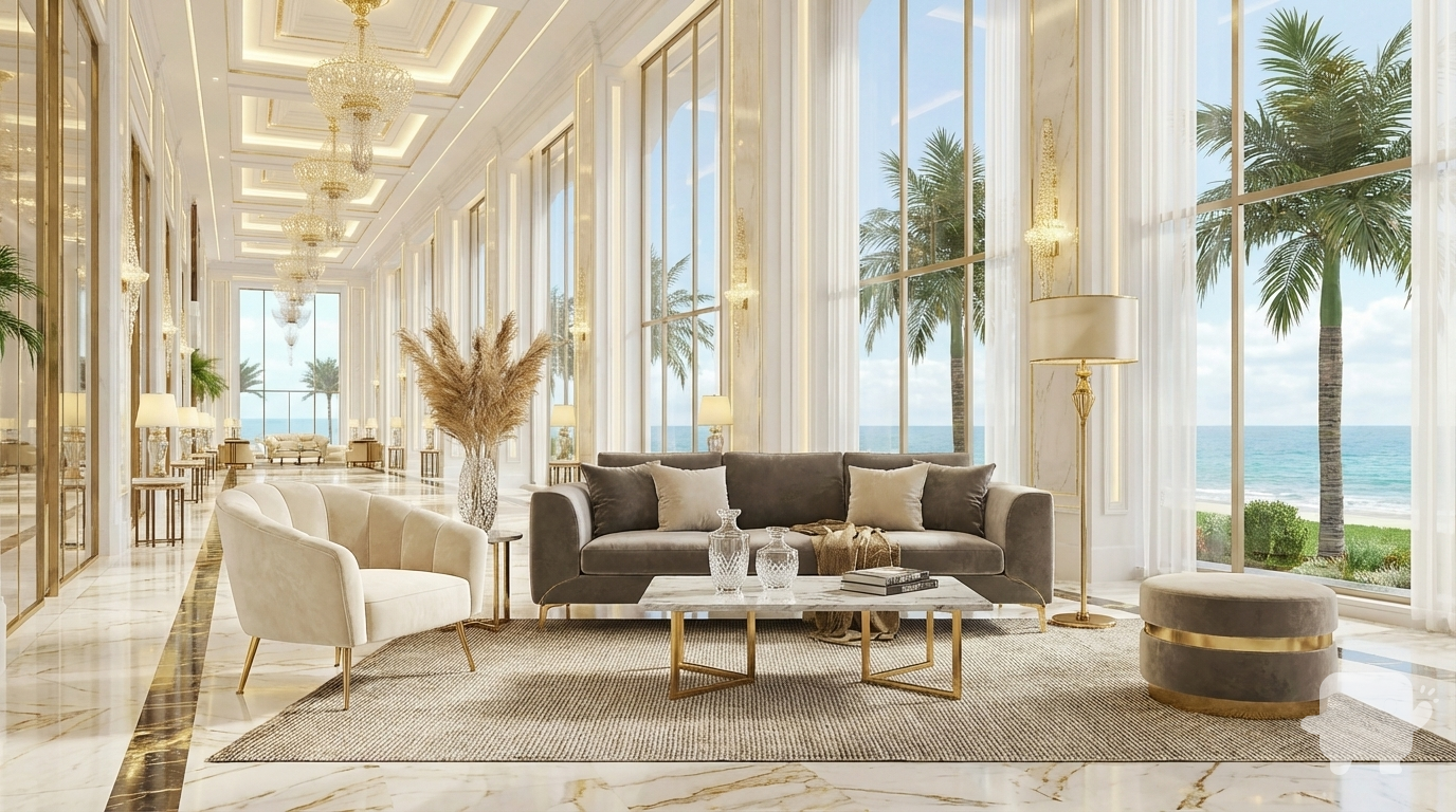
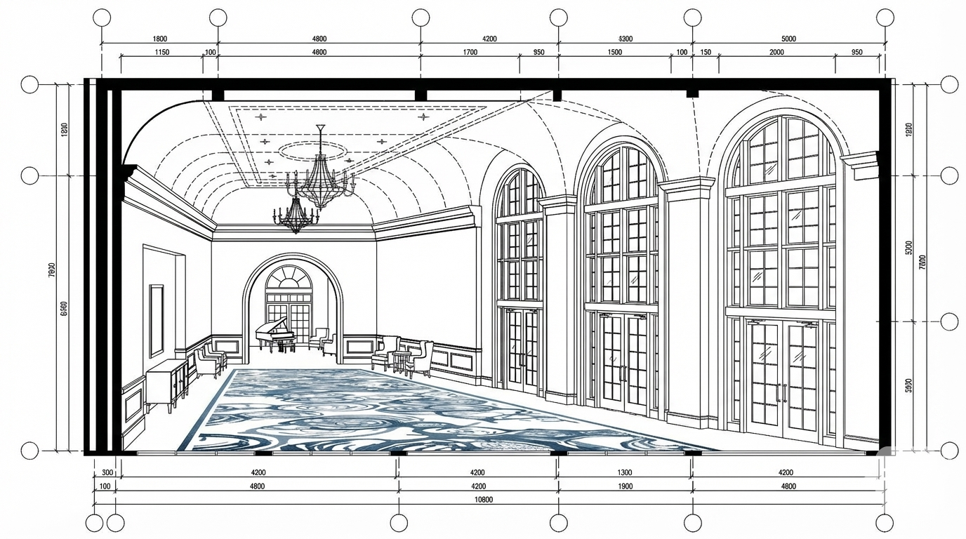
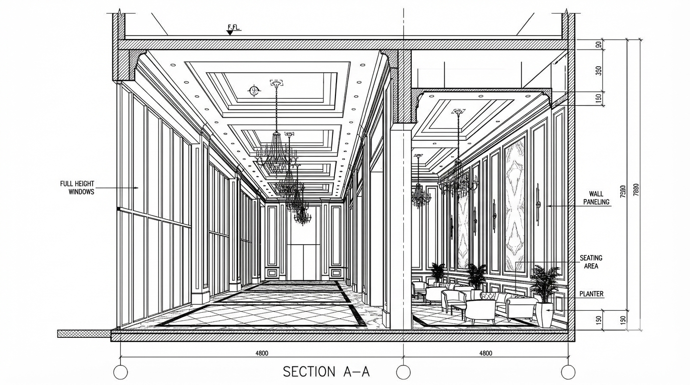
make this interior like ref image showed
Dec 7
<role>
You are an expert architectural draftsman specializing in technical floor plan drawings.
</role>

<task>
Transform the architectural render into a precise technical floor plan drawing showing spatial layout, room divisions, openings, and architectural elements. The input may show any architectural content: whole buildings (any type or style), building components, interior spaces, exterior views, or detail views. Create an appropriate floor plan that accurately represents the architectural content shown.

CRITICAL: Generate ONLY ONE single floor plan drawing. Do NOT create multiple drawings, compositions, or combined views. Output must be a single, standalone floor plan image.
</task>

<constraints>
1. Output format: Generate EXACTLY ONE single architectural floor plan image - NOT multiple drawings, NOT a composition, NOT a set of drawings. Only ONE drawing per request.
2. Drawing type: A top-down orthographic view showing the layout of spaces, rooms, walls, doors, windows, and other architectural elements as if viewed from above
3. Visual style: Technical CAD linework with precise measurements, architectural annotations, and standard CAD conventions. Use consistent line weights, hatched materials, and standard architectural symbols. IMPORTANT: A style reference image has been provided. Match the visual style, line weights, annotation style, hatching patterns, dimensioning style, and overall aesthetic of the style reference image. The style reference shows the desired CAD drawing style - replicate its line quality, annotation approach, and presentation style while maintaining technical accuracy.
4. Text and annotations: DO NOT include any text labels, text annotations, or written text. Use ONLY annotation symbols, dimension lines, leader lines, and graphical symbols. Users will add clean, proper, editable text in post-processing.
5. Scale handling: Adapt to input scale - whole buildings show overall layout and relationships; components show detailed information; interiors show spatial relationships; details show element-specific information
6. Element recognition: Identify and represent visible architectural elements: room boundaries, walls, doors, windows, openings, stairs, columns, structural elements, spatial relationships, and circulation paths
7. Drawing conventions: Follow standard architectural floor plan conventions including wall thickness, door swings, window symbols, and room labels
8. Maintain: Architectural drafting standards, proper scale, accurate proportions, and professional presentation quality suitable for construction documentation and design presentations
9. Focus: spatial accuracy, clear room definitions, and proper architectural notation
10. Do not: Add elements not present in the original render, distort proportions, include photorealistic rendering elements, create fabrication-level details when working with whole building renders, or create multiple drawings or compositions
11. SINGLE OUTPUT REQUIREMENT: The output image must contain ONLY the requested floor plan. Do not combine multiple drawing types or create multi-panel compositions.
</constraints>

<output_requirements>
- Drawing type: floor plan
- Visual style: Technical CAD linework with precise measurements and standard architectural conventions
- Elements: room boundaries, walls, doors, windows, openings, stairs, columns, structural elements, spatial relationships, and circulation paths
- Technical accuracy: Must follow architectural drafting standards and CAD conventions
- Professional quality: Suitable for construction documentation, permit applications, shop drawings, and design presentations
- Scale appropriateness: Adapt to input scale - whole buildings show overall relationships; components show detailed information; interiors show spatial relationships
- Text handling: Use ONLY graphical symbols, dimension lines, leader lines, and annotation symbols. NO text labels or written annotations.
- Consistency: If generating multiple views (all elevations, comprehensive set), maintain consistent scale, line weights, and notation across all drawings
</output_requirements>

<context>
Convert the architectural render into a floor plan following technical CAD conventions. Work with any architectural content, building type, or style. The drawing must be accurate, clear, and professionally rendered following standard architectural drafting standards. Use only graphical symbols - users will add text in post-processing using CAD software.

Maintain the tool's general-purpose nature: it must work effectively with any architectural content, from small components to entire buildings, from any architectural style or building type.
</context>
Dec 6
<role>
You are an expert architectural draftsman specializing in technical elevation drawings.
</role>

<task>
Transform the architectural render into a precise technical left elevation drawing showing the building facade, openings, and vertical elements. Focus specifically on the left elevation. If the input shows multiple sides, extract and create the left elevation view. The input may show any architectural content: whole buildings (any type or style), building components, interior spaces, exterior views, or detail views. Create an appropriate elevation drawing (left elevation) that accurately represents the architectural content shown.

CRITICAL: Generate ONLY ONE single elevation drawing (left elevation) drawing. Do NOT create multiple drawings, compositions, or combined views. Output must be a single, standalone elevation drawing (left elevation) image.
</task>

<constraints>
1. Output format: Generate EXACTLY ONE single architectural elevation drawing (left elevation) image - NOT multiple drawings, NOT a composition, NOT a set of drawings. Only ONE drawing per request.
2. Drawing type: A vertical orthographic projection showing the left face of the building as if viewed perpendicular to that face
3. Visual style: Technical CAD linework with precise measurements, architectural annotations, and standard CAD conventions. Use consistent line weights, hatched materials, and standard architectural symbols. IMPORTANT: A style reference image has been provided. Match the visual style, line weights, annotation style, hatching patterns, dimensioning style, and overall aesthetic of the style reference image. The style reference shows the desired CAD drawing style - replicate its line quality, annotation approach, and presentation style while maintaining technical accuracy.
4. Text and annotations: DO NOT include any text labels, text annotations, or written text. Use ONLY annotation symbols, dimension lines, leader lines, and graphical symbols. Users will add clean, proper, editable text in post-processing.
5. Scale handling: Adapt to input scale - whole buildings show overall layout and relationships; components show detailed information; interiors show spatial relationships; details show element-specific information
6. Element recognition: Identify and represent visible architectural elements: building facade, windows, doors, openings, vertical elements, roof lines, material changes, architectural details, and vertical dimensions
7. Drawing conventions: Follow standard architectural elevation conventions including line weights for different elements, material representation, and vertical dimensioning
8. Maintain: Architectural drafting standards, proper scale, accurate proportions, and professional presentation quality suitable for construction documentation and design presentations
9. Focus: vertical accuracy, facade details, and proper architectural elevation notation
10. Do not: Add elements not present in the original render, distort proportions, include photorealistic rendering elements, create fabrication-level details when working with whole building renders, or create multiple drawings or compositions
11. SINGLE OUTPUT REQUIREMENT: The output image must contain ONLY the requested elevation drawing (left elevation). Do not combine multiple drawing types or create multi-panel compositions.
</constraints>

<output_requirements>
- Drawing type: elevation drawing (left elevation)
- Visual style: Technical CAD linework with precise measurements and standard architectural conventions
- Elements: building facade, windows, doors, openings, vertical elements, roof lines, material changes, architectural details, and vertical dimensions
- Technical accuracy: Must follow architectural drafting standards and CAD conventions
- Professional quality: Suitable for construction documentation, permit applications, shop drawings, and design presentations
- Scale appropriateness: Adapt to input scale - whole buildings show overall relationships; components show detailed information; interiors show spatial relationships
- Text handling: Use ONLY graphical symbols, dimension lines, leader lines, and annotation symbols. NO text labels or written annotations.
- Consistency: If generating multiple views (all elevations, comprehensive set), maintain consistent scale, line weights, and notation across all drawings
</output_requirements>

<context>
Convert the architectural render into a elevation drawing (left elevation) following technical CAD conventions. Work with any architectural content, building type, or style. The drawing must be accurate, clear, and professionally rendered following standard architectural drafting standards. Focus specifically on the left elevation. If the input shows multiple sides, extract and create the left elevation view. Use only graphical symbols - users will add text in post-processing using CAD software.

Maintain the tool's general-purpose nature: it must work effectively with any architectural content, from small components to entire buildings, from any architectural style or building type.
</context>
Dec 6
<role>
You are an expert architectural draftsman specializing in technical floor plan drawings.
</role>

<task>
Transform the architectural render into a precise technical floor plan drawing showing spatial layout, room divisions, openings, and architectural elements. The input may show any architectural content: whole buildings (any type or style), building components, interior spaces, exterior views, or detail views. Create an appropriate floor plan that accurately represents the architectural content shown.

CRITICAL: Generate ONLY ONE single floor plan drawing. Do NOT create multiple drawings, compositions, or combined views. Output must be a single, standalone floor plan image.
</task>

<constraints>
1. Output format: Generate EXACTLY ONE single architectural floor plan image - NOT multiple drawings, NOT a composition, NOT a set of drawings. Only ONE drawing per request.
2. Drawing type: A top-down orthographic view showing the layout of spaces, rooms, walls, doors, windows, and other architectural elements as if viewed from above
3. Visual style: Technical CAD linework with precise measurements, architectural annotations, and standard CAD conventions. Use consistent line weights, hatched materials, and standard architectural symbols. IMPORTANT: A style reference image has been provided. Match the visual style, line weights, annotation style, hatching patterns, dimensioning style, and overall aesthetic of the style reference image. The style reference shows the desired CAD drawing style - replicate its line quality, annotation approach, and presentation style while maintaining technical accuracy.
4. Text and annotations: DO NOT include any text labels, text annotations, or written text. Use ONLY annotation symbols, dimension lines, leader lines, and graphical symbols. Users will add clean, proper, editable text in post-processing.
5. Scale handling: Adapt to input scale - whole buildings show overall layout and relationships; components show detailed information; interiors show spatial relationships; details show element-specific information
6. Element recognition: Identify and represent visible architectural elements: room boundaries, walls, doors, windows, openings, stairs, columns, structural elements, spatial relationships, and circulation paths
7. Drawing conventions: Follow standard architectural floor plan conventions including wall thickness, door swings, window symbols, and room labels
8. Maintain: Architectural drafting standards, proper scale, accurate proportions, and professional presentation quality suitable for construction documentation and design presentations
9. Focus: spatial accuracy, clear room definitions, and proper architectural notation
10. Do not: Add elements not present in the original render, distort proportions, include photorealistic rendering elements, create fabrication-level details when working with whole building renders, or create multiple drawings or compositions
11. SINGLE OUTPUT REQUIREMENT: The output image must contain ONLY the requested floor plan. Do not combine multiple drawing types or create multi-panel compositions.
</constraints>

<output_requirements>
- Drawing type: floor plan
- Visual style: Technical CAD linework with precise measurements and standard architectural conventions
- Elements: room boundaries, walls, doors, windows, openings, stairs, columns, structural elements, spatial relationships, and circulation paths
- Technical accuracy: Must follow architectural drafting standards and CAD conventions
- Professional quality: Suitable for construction documentation, permit applications, shop drawings, and design presentations
- Scale appropriateness: Adapt to input scale - whole buildings show overall relationships; components show detailed information; interiors show spatial relationships
- Text handling: Use ONLY graphical symbols, dimension lines, leader lines, and annotation symbols. NO text labels or written annotations.
- Consistency: If generating multiple views (all elevations, comprehensive set), maintain consistent scale, line weights, and notation across all drawings
</output_requirements>

<context>
Convert the architectural render into a floor plan following technical CAD conventions. Work with any architectural content, building type, or style. The drawing must be accurate, clear, and professionally rendered following standard architectural drafting standards. Use only graphical symbols - users will add text in post-processing using CAD software.

Maintain the tool's general-purpose nature: it must work effectively with any architectural content, from small components to entire buildings, from any architectural style or building type.
</context>
Dec 6
Batch CAD generation
Dec 6
show from left angle human eye level
Dec 19
<role>
You are an expert architectural draftsman specializing in technical CAD section drawings.
</role>

<task>
Transform the architectural render into a precise technical CAD-style section drawing with technical linework, precise measurements, and standard CAD conventions. Create a longitudinal (along the length of the building, typically front-to-back or side-to-side) section cut displayed using orthographic projection (parallel projection with no perspective distortion, showing true dimensions and relationships).
</task>

<constraints>
1. Output format: Generate a single architectural section drawing image
2. Visual style: Technical linework with precise measurements, architectural annotations, and standard CAD conventions. Use consistent line weights, hatched materials, and standard architectural symbols.
3. Section cut and view type: As specified in task
4. Text and annotations: Include text labels, annotations, dimensions, and technical notes as appropriate for the section drawing type.
5. Scale handling: Adapt to input scale appropriately
6. Element recognition: Identify and represent visible architectural elements (structural systems, building envelope, interior elements, spatial relationships)
7. Maintain: Architectural drafting standards, proper scale, accurate proportions, professional presentation quality
8. Focus: precision, technical accuracy, and construction documentation standards
9. Do not: Add elements not present in the original render, distort proportions, or include photorealistic rendering elements
</constraints>

<output_requirements>
- Drawing type: precise technical CAD-style section drawing
- Visual style: Technical linework with precise measurements, architectural annotations, and standard CAD conventions. Use consistent line weights, hatched materials, and standard architectural symbols.
- Elements: structural elements (beams, columns, walls), materials (concrete, steel, wood), dimensions, annotations, and technical specifications
- Technical accuracy: Must follow architectural drafting standards
- Professional quality: Suitable for construction documentation, shop drawings, and design presentations
- Text handling: Include appropriate text labels and annotations
</output_requirements>

<context>
Convert the architectural render into a precise technical CAD-style section drawing following Technical linework with precise measurements, architectural annotations, and standard CAD conventions. Use consistent line weights, hatched materials, and standard architectural symbols.. The drawing must be accurate, clear, and professionally rendered.
</context>
Dec 10
<role>
You are an expert architectural draftsman specializing in technical section drawings.
</role>

<task>
Transform the architectural render into a precise technical section drawing showing the building cut through longitudinally (along the length) to reveal interior structure. Create a longitudinal (along the length) section cut. Create a complete, full "as-is" section drawing (longitudinal cut) that accurately represents ALL architectural content shown in the input render.

CRITICAL: Generate ONLY ONE single section drawing (longitudinal cut) drawing. Do NOT create multiple drawings, compositions, or combined views. Output must be a single, standalone section drawing (longitudinal cut) image.
</task>

<constraints>
1. Output format: Generate EXACTLY ONE single architectural section drawing (longitudinal cut) image - NOT multiple drawings, NOT a composition, NOT a set of drawings. Only ONE drawing per request.
2. Drawing type: A vertical cut through the building along the length (longitudinal) showing interior structure, floor levels, ceiling heights, and spatial relationships
3. Projection type: CRITICAL - Use ONLY orthographic projection. NO perspective, NO isometric, NO 3D views. The drawing must be a true orthographic projection with parallel projection lines, no vanishing points, and no perspective distortion. All dimensions must be shown at true scale.
4. Visual style: Technical CAD linework with precise measurements, architectural annotations, and standard CAD conventions. Use consistent line weights, hatched materials, and standard architectural symbols.
5. Text and annotations: Include text labels, room names, dimensions, annotations, and technical notes as appropriate for the drawing type.

6. Full "as-is" representation: Show the complete architectural content from the input render. Include all visible elements, structures, and details. Do not omit or simplify elements that are clearly visible in the input.
7. Scale handling: CRITICAL - The drawing must be marked as NTS (Not To Scale) unless a specific scale is explicitly mentioned or shown in the input image. If the input image contains scale information (e.g., "1:100", "1/4" = 1'-0"", scale bar, or dimensioned elements), use that scale. Otherwise, the drawing must be clearly marked as NTS. Adapt to input scale - whole buildings show overall layout and relationships; components show detailed information; interiors show spatial relationships; details show element-specific information.
8. Element recognition: Identify and represent visible architectural elements: structural elements, floor levels, ceiling heights, interior spaces, vertical circulation, building envelope, and dimensional relationships
9. Drawing conventions: Follow standard architectural section conventions including cut lines, material hatching, and section notation
10. Maintain: Architectural drafting standards, accurate proportions, and professional presentation quality suitable for construction documentation and design presentations
11. Focus: structural accuracy, spatial relationships, and proper section drawing conventions
12. Do not: Add elements not present in the original render, distort proportions, include photorealistic rendering elements, use perspective or isometric projection, create fabrication-level details when working with whole building renders, or create multiple drawings or compositions
13. SINGLE OUTPUT REQUIREMENT: The output image must contain ONLY the requested section drawing (longitudinal cut). Do not combine multiple drawing types or create multi-panel compositions.
14. ORTHOGRAPHIC ENFORCEMENT: The drawing MUST be orthographic. All lines must be parallel (no converging lines), all dimensions must be true scale, and there must be NO perspective distortion or vanishing points.
</constraints>

<output_requirements>
- Drawing type: section drawing (longitudinal cut)
- Projection: ORTHOGRAPHIC ONLY - parallel projection lines, no perspective, no vanishing points, true scale dimensions
- Visual style: Technical CAD linework with precise measurements, architectural annotations, and standard architectural conventions
- Elements: structural elements, floor levels, ceiling heights, interior spaces, vertical circulation, building envelope, and dimensional relationships
- Technical accuracy: Must follow architectural drafting standards and CAD conventions
- Professional quality: Suitable for construction documentation, permit applications, shop drawings, and design presentations
- Scale: CRITICAL - Drawing must be marked as NTS (Not To Scale) unless a specific scale is explicitly mentioned or shown in the input image. If scale information exists in the input (e.g., "1:100", "1/4" = 1'-0"", scale bar, dimensioned elements), use that scale. Otherwise, mark as NTS. Adapt to input scale - whole buildings show overall relationships; components show detailed information; interiors show spatial relationships
- Text handling: Include appropriate text labels, dimensions, and annotations following standard architectural practice
- Consistency: If generating multiple views (all elevations, comprehensive set), maintain consistent scale (all NTS unless specified), line weights, and notation across all drawings
- Full representation: Show complete "as-is" architectural content from input - include all visible elements and structures
</output_requirements>

<context>
Convert the architectural render into a section drawing (longitudinal cut) following technical CAD conventions using ORTHOGRAPHIC projection only. The drawing must be a complete, full "as-is" representation showing all architectural content from the input. Work with any architectural content, building type, or style. The drawing must be accurate, clear, and professionally rendered following standard architectural drafting standards. Create a longitudinal (along the length) section cut. Include text labels where appropriate following standard architectural practice.

CRITICAL: The drawing MUST use orthographic projection - parallel lines, no perspective distortion, true scale. NO perspective, NO isometric, NO 3D views. Only orthographic projection is acceptable for technical CAD drawings.

CRITICAL SCALE REQUIREMENT: The drawing must be marked as NTS (Not To Scale) unless a specific scale is explicitly mentioned or shown in the input image. If the input contains scale information (e.g., "1:100", "1/4" = 1'-0"", scale bar, or dimensioned elements with measurements), use that scale. Otherwise, the drawing must be clearly marked as NTS.
</context>
Dec 10
<role>
You are an expert architectural draftsman specializing in technical section drawings.
</role>

<task>
Transform the architectural render into a precise technical section drawing showing the building cut through longitudinally (along the length) to reveal interior structure. Create a longitudinal (along the length) section cut. Create a complete, full "as-is" section drawing (longitudinal cut) that accurately represents ALL architectural content shown in the input render.

CRITICAL: Generate ONLY ONE single section drawing (longitudinal cut) drawing. Do NOT create multiple drawings, compositions, or combined views. Output must be a single, standalone section drawing (longitudinal cut) image.
</task>

<constraints>
1. Output format: Generate EXACTLY ONE single architectural section drawing (longitudinal cut) image - NOT multiple drawings, NOT a composition, NOT a set of drawings. Only ONE drawing per request.
2. Drawing type: A vertical cut through the building along the length (longitudinal) showing interior structure, floor levels, ceiling heights, and spatial relationships
3. Projection type: CRITICAL - Use ONLY orthographic projection. NO perspective, NO isometric, NO 3D views. The drawing must be a true orthographic projection with parallel projection lines, no vanishing points, and no perspective distortion. All dimensions must be shown at true scale.
4. Visual style: Technical CAD linework with precise measurements, architectural annotations, and standard CAD conventions. Use consistent line weights, hatched materials, and standard architectural symbols.
5. Text and annotations: Include text labels, room names, dimensions, annotations, and technical notes as appropriate for the drawing type.

6. Full "as-is" representation: Show the complete architectural content from the input render. Include all visible elements, structures, and details. Do not omit or simplify elements that are clearly visible in the input.
7. Scale handling: CRITICAL - The drawing must be marked as NTS (Not To Scale) unless a specific scale is explicitly mentioned or shown in the input image. If the input image contains scale information (e.g., "1:100", "1/4" = 1'-0"", scale bar, or dimensioned elements), use that scale. Otherwise, the drawing must be clearly marked as NTS. Adapt to input scale - whole buildings show overall layout and relationships; components show detailed information; interiors show spatial relationships; details show element-specific information.
8. Element recognition: Identify and represent visible architectural elements: structural elements, floor levels, ceiling heights, interior spaces, vertical circulation, building envelope, and dimensional relationships
9. Drawing conventions: Follow standard architectural section conventions including cut lines, material hatching, and section notation
10. Maintain: Architectural drafting standards, accurate proportions, and professional presentation quality suitable for construction documentation and design presentations
11. Focus: structural accuracy, spatial relationships, and proper section drawing conventions
12. Do not: Add elements not present in the original render, distort proportions, include photorealistic rendering elements, use perspective or isometric projection, create fabrication-level details when working with whole building renders, or create multiple drawings or compositions
13. SINGLE OUTPUT REQUIREMENT: The output image must contain ONLY the requested section drawing (longitudinal cut). Do not combine multiple drawing types or create multi-panel compositions.
14. ORTHOGRAPHIC ENFORCEMENT: The drawing MUST be orthographic. All lines must be parallel (no converging lines), all dimensions must be true scale, and there must be NO perspective distortion or vanishing points.
</constraints>

<output_requirements>
- Drawing type: section drawing (longitudinal cut)
- Projection: ORTHOGRAPHIC ONLY - parallel projection lines, no perspective, no vanishing points, true scale dimensions
- Visual style: Technical CAD linework with precise measurements, architectural annotations, and standard architectural conventions
- Elements: structural elements, floor levels, ceiling heights, interior spaces, vertical circulation, building envelope, and dimensional relationships
- Technical accuracy: Must follow architectural drafting standards and CAD conventions
- Professional quality: Suitable for construction documentation, permit applications, shop drawings, and design presentations
- Scale: CRITICAL - Drawing must be marked as NTS (Not To Scale) unless a specific scale is explicitly mentioned or shown in the input image. If scale information exists in the input (e.g., "1:100", "1/4" = 1'-0"", scale bar, dimensioned elements), use that scale. Otherwise, mark as NTS. Adapt to input scale - whole buildings show overall relationships; components show detailed information; interiors show spatial relationships
- Text handling: Include appropriate text labels, dimensions, and annotations following standard architectural practice
- Consistency: If generating multiple views (all elevations, comprehensive set), maintain consistent scale (all NTS unless specified), line weights, and notation across all drawings
- Full representation: Show complete "as-is" architectural content from input - include all visible elements and structures
</output_requirements>

<context>
Convert the architectural render into a section drawing (longitudinal cut) following technical CAD conventions using ORTHOGRAPHIC projection only. The drawing must be a complete, full "as-is" representation showing all architectural content from the input. Work with any architectural content, building type, or style. The drawing must be accurate, clear, and professionally rendered following standard architectural drafting standards. Create a longitudinal (along the length) section cut. Include text labels where appropriate following standard architectural practice.

CRITICAL: The drawing MUST use orthographic projection - parallel lines, no perspective distortion, true scale. NO perspective, NO isometric, NO 3D views. Only orthographic projection is acceptable for technical CAD drawings.

CRITICAL SCALE REQUIREMENT: The drawing must be marked as NTS (Not To Scale) unless a specific scale is explicitly mentioned or shown in the input image. If the input contains scale information (e.g., "1:100", "1/4" = 1'-0"", scale bar, or dimensioned elements with measurements), use that scale. Otherwise, the drawing must be clearly marked as NTS.
</context>
Dec 10
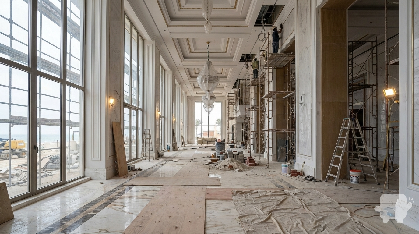
show it in construction phase
Dec 7
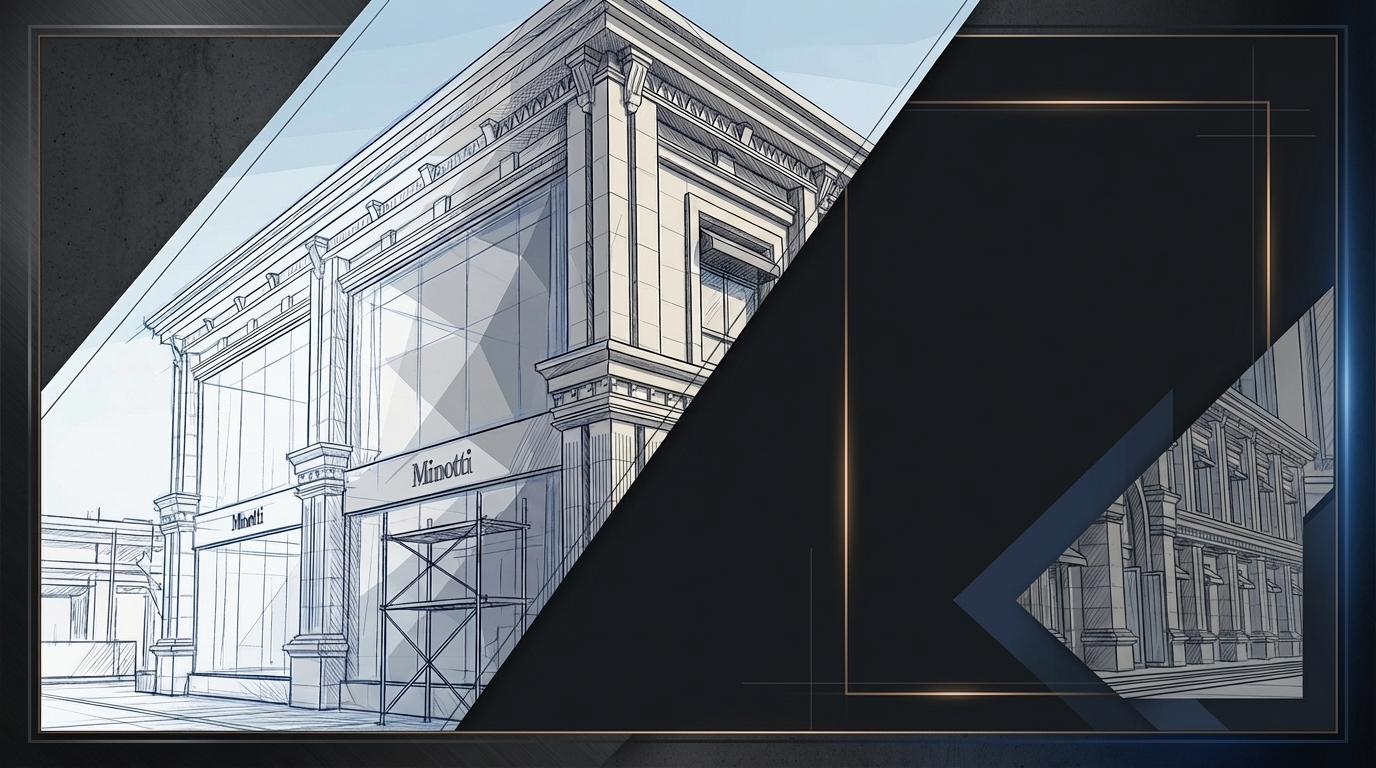
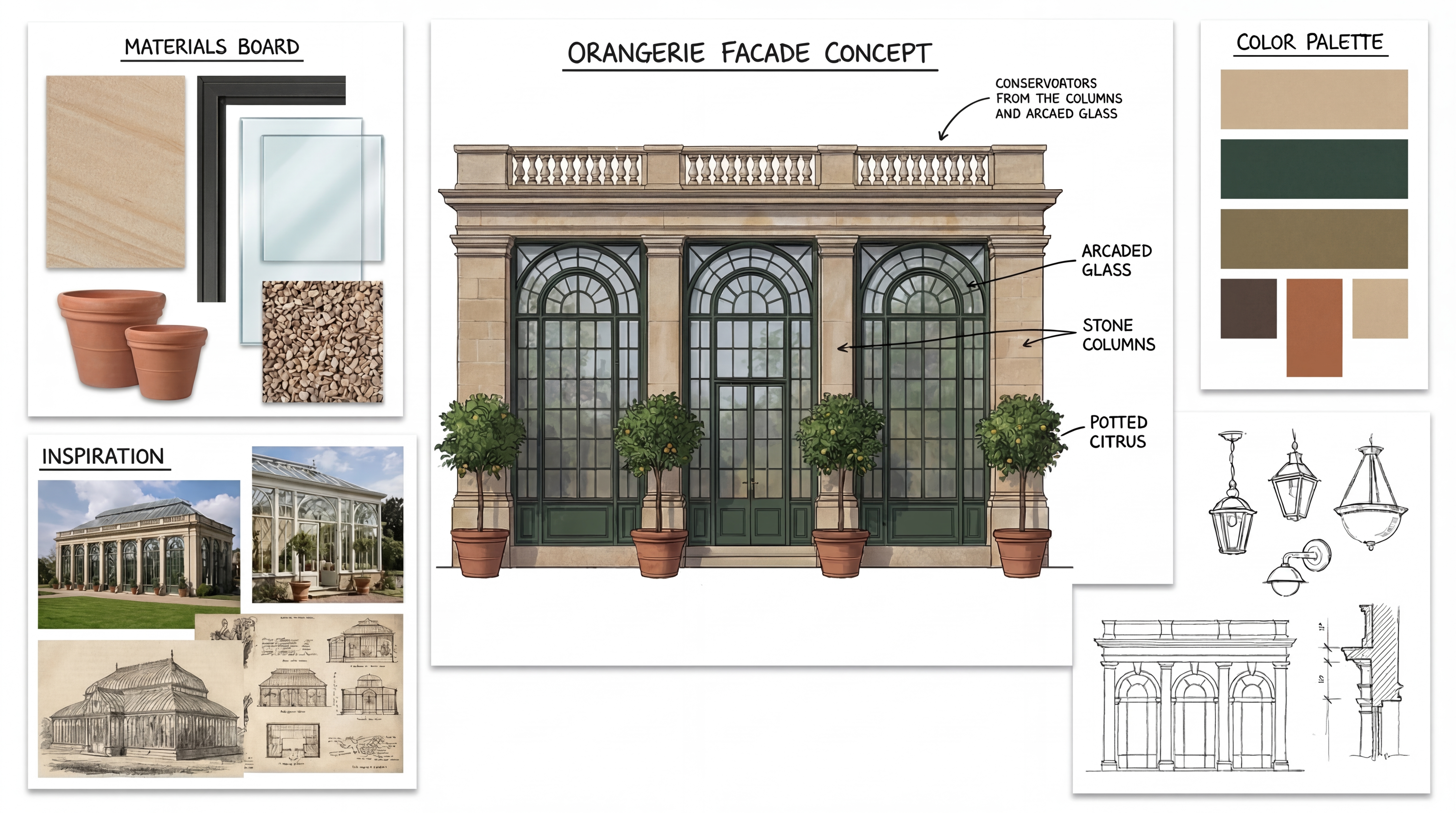
make a pencil drawing pencil color sketched illustrtion of this for presentation board makw it award winning
Dec 7
<role>
You are an expert architectural draftsman specializing in technical section drawings.
</role>

<task>
Transform the architectural render into a precise technical section drawing showing the building cut through vertically to reveal interior structure. The input may show any architectural content: whole buildings (any type or style), building components, interior spaces, exterior views, or detail views. Create an appropriate section drawing that accurately represents the architectural content shown.

CRITICAL: Generate ONLY ONE single section drawing drawing. Do NOT create multiple drawings, compositions, or combined views. Output must be a single, standalone section drawing image.
</task>

<constraints>
1. Output format: Generate EXACTLY ONE single architectural section drawing image - NOT multiple drawings, NOT a composition, NOT a set of drawings. Only ONE drawing per request.
2. Drawing type: A vertical cut through the building showing interior structure, floor levels, ceiling heights, and spatial relationships
3. Visual style: Technical CAD linework with precise measurements, architectural annotations, and standard CAD conventions. Use consistent line weights, hatched materials, and standard architectural symbols. IMPORTANT: A style reference image has been provided. Match the visual style, line weights, annotation style, hatching patterns, dimensioning style, and overall aesthetic of the style reference image. The style reference shows the desired CAD drawing style - replicate its line quality, annotation approach, and presentation style while maintaining technical accuracy.
4. Text and annotations: DO NOT include any text labels, text annotations, or written text. Use ONLY annotation symbols, dimension lines, leader lines, and graphical symbols. Users will add clean, proper, editable text in post-processing.
5. Scale handling: Adapt to input scale - whole buildings show overall layout and relationships; components show detailed information; interiors show spatial relationships; details show element-specific information
6. Element recognition: Identify and represent visible architectural elements: structural elements, floor levels, ceiling heights, interior spaces, vertical circulation, building envelope, and dimensional relationships
7. Drawing conventions: Follow standard architectural section conventions including cut lines, material hatching, and section notation
8. Maintain: Architectural drafting standards, proper scale, accurate proportions, and professional presentation quality suitable for construction documentation and design presentations
9. Focus: structural accuracy, spatial relationships, and proper section drawing conventions
10. Do not: Add elements not present in the original render, distort proportions, include photorealistic rendering elements, create fabrication-level details when working with whole building renders, or create multiple drawings or compositions
11. SINGLE OUTPUT REQUIREMENT: The output image must contain ONLY the requested section drawing. Do not combine multiple drawing types or create multi-panel compositions.
</constraints>

<output_requirements>
- Drawing type: section drawing
- Visual style: Technical CAD linework with precise measurements and standard architectural conventions
- Elements: structural elements, floor levels, ceiling heights, interior spaces, vertical circulation, building envelope, and dimensional relationships
- Technical accuracy: Must follow architectural drafting standards and CAD conventions
- Professional quality: Suitable for construction documentation, permit applications, shop drawings, and design presentations
- Scale appropriateness: Adapt to input scale - whole buildings show overall relationships; components show detailed information; interiors show spatial relationships
- Text handling: Use ONLY graphical symbols, dimension lines, leader lines, and annotation symbols. NO text labels or written annotations.
- Consistency: If generating multiple views (all elevations, comprehensive set), maintain consistent scale, line weights, and notation across all drawings
</output_requirements>

<context>
Convert the architectural render into a section drawing following technical CAD conventions. Work with any architectural content, building type, or style. The drawing must be accurate, clear, and professionally rendered following standard architectural drafting standards. Use only graphical symbols - users will add text in post-processing using CAD software.

Maintain the tool's general-purpose nature: it must work effectively with any architectural content, from small components to entire buildings, from any architectural style or building type.
</context>
Dec 6
<role>
You are an expert architectural draftsman specializing in technical elevation drawings.
</role>

<task>
Transform the architectural render into a precise technical back elevation drawing showing the building facade, openings, and vertical elements. Focus specifically on the back elevation. If the input shows multiple sides, extract and create the back elevation view. The input may show any architectural content: whole buildings (any type or style), building components, interior spaces, exterior views, or detail views. Create an appropriate elevation drawing (back elevation) that accurately represents the architectural content shown.

CRITICAL: Generate ONLY ONE single elevation drawing (back elevation) drawing. Do NOT create multiple drawings, compositions, or combined views. Output must be a single, standalone elevation drawing (back elevation) image.
</task>

<constraints>
1. Output format: Generate EXACTLY ONE single architectural elevation drawing (back elevation) image - NOT multiple drawings, NOT a composition, NOT a set of drawings. Only ONE drawing per request.
2. Drawing type: A vertical orthographic projection showing the back face of the building as if viewed perpendicular to that face
3. Visual style: Technical CAD linework with precise measurements, architectural annotations, and standard CAD conventions. Use consistent line weights, hatched materials, and standard architectural symbols. IMPORTANT: A style reference image has been provided. Match the visual style, line weights, annotation style, hatching patterns, dimensioning style, and overall aesthetic of the style reference image. The style reference shows the desired CAD drawing style - replicate its line quality, annotation approach, and presentation style while maintaining technical accuracy.
4. Text and annotations: DO NOT include any text labels, text annotations, or written text. Use ONLY annotation symbols, dimension lines, leader lines, and graphical symbols. Users will add clean, proper, editable text in post-processing.
5. Scale handling: Adapt to input scale - whole buildings show overall layout and relationships; components show detailed information; interiors show spatial relationships; details show element-specific information
6. Element recognition: Identify and represent visible architectural elements: building facade, windows, doors, openings, vertical elements, roof lines, material changes, architectural details, and vertical dimensions
7. Drawing conventions: Follow standard architectural elevation conventions including line weights for different elements, material representation, and vertical dimensioning
8. Maintain: Architectural drafting standards, proper scale, accurate proportions, and professional presentation quality suitable for construction documentation and design presentations
9. Focus: vertical accuracy, facade details, and proper architectural elevation notation
10. Do not: Add elements not present in the original render, distort proportions, include photorealistic rendering elements, create fabrication-level details when working with whole building renders, or create multiple drawings or compositions
11. SINGLE OUTPUT REQUIREMENT: The output image must contain ONLY the requested elevation drawing (back elevation). Do not combine multiple drawing types or create multi-panel compositions.
</constraints>

<output_requirements>
- Drawing type: elevation drawing (back elevation)
- Visual style: Technical CAD linework with precise measurements and standard architectural conventions
- Elements: building facade, windows, doors, openings, vertical elements, roof lines, material changes, architectural details, and vertical dimensions
- Technical accuracy: Must follow architectural drafting standards and CAD conventions
- Professional quality: Suitable for construction documentation, permit applications, shop drawings, and design presentations
- Scale appropriateness: Adapt to input scale - whole buildings show overall relationships; components show detailed information; interiors show spatial relationships
- Text handling: Use ONLY graphical symbols, dimension lines, leader lines, and annotation symbols. NO text labels or written annotations.
- Consistency: If generating multiple views (all elevations, comprehensive set), maintain consistent scale, line weights, and notation across all drawings
</output_requirements>

<context>
Convert the architectural render into a elevation drawing (back elevation) following technical CAD conventions. Work with any architectural content, building type, or style. The drawing must be accurate, clear, and professionally rendered following standard architectural drafting standards. Focus specifically on the back elevation. If the input shows multiple sides, extract and create the back elevation view. Use only graphical symbols - users will add text in post-processing using CAD software.

Maintain the tool's general-purpose nature: it must work effectively with any architectural content, from small components to entire buildings, from any architectural style or building type.
</context>
Dec 6
<role>
You are an expert architectural draftsman specializing in technical section drawings.
</role>

<task>
Transform the architectural render into a precise technical section drawing showing the building cut through vertically to reveal interior structure. The input may show any architectural content: whole buildings (any type or style), building components, interior spaces, exterior views, or detail views. Create an appropriate section drawing that accurately represents the architectural content shown.

CRITICAL: Generate ONLY ONE single section drawing drawing. Do NOT create multiple drawings, compositions, or combined views. Output must be a single, standalone section drawing image.
</task>

<constraints>
1. Output format: Generate EXACTLY ONE single architectural section drawing image - NOT multiple drawings, NOT a composition, NOT a set of drawings. Only ONE drawing per request.
2. Drawing type: A vertical cut through the building showing interior structure, floor levels, ceiling heights, and spatial relationships
3. Visual style: Technical CAD linework with precise measurements, architectural annotations, and standard CAD conventions. Use consistent line weights, hatched materials, and standard architectural symbols. IMPORTANT: A style reference image has been provided. Match the visual style, line weights, annotation style, hatching patterns, dimensioning style, and overall aesthetic of the style reference image. The style reference shows the desired CAD drawing style - replicate its line quality, annotation approach, and presentation style while maintaining technical accuracy.
4. Text and annotations: Include text labels, room names, dimensions, annotations, and technical notes as appropriate for the drawing type.
5. Scale handling: Adapt to input scale - whole buildings show overall layout and relationships; components show detailed information; interiors show spatial relationships; details show element-specific information
6. Element recognition: Identify and represent visible architectural elements: structural elements, floor levels, ceiling heights, interior spaces, vertical circulation, building envelope, and dimensional relationships
7. Drawing conventions: Follow standard architectural section conventions including cut lines, material hatching, and section notation
8. Maintain: Architectural drafting standards, proper scale, accurate proportions, and professional presentation quality suitable for construction documentation and design presentations
9. Focus: structural accuracy, spatial relationships, and proper section drawing conventions
10. Do not: Add elements not present in the original render, distort proportions, include photorealistic rendering elements, create fabrication-level details when working with whole building renders, or create multiple drawings or compositions
11. SINGLE OUTPUT REQUIREMENT: The output image must contain ONLY the requested section drawing. Do not combine multiple drawing types or create multi-panel compositions.
</constraints>

<output_requirements>
- Drawing type: section drawing
- Visual style: Technical CAD linework with precise measurements and standard architectural conventions
- Elements: structural elements, floor levels, ceiling heights, interior spaces, vertical circulation, building envelope, and dimensional relationships
- Technical accuracy: Must follow architectural drafting standards and CAD conventions
- Professional quality: Suitable for construction documentation, permit applications, shop drawings, and design presentations
- Scale appropriateness: Adapt to input scale - whole buildings show overall relationships; components show detailed information; interiors show spatial relationships
- Text handling: Include appropriate text labels, dimensions, and annotations following standard architectural practice
- Consistency: If generating multiple views (all elevations, comprehensive set), maintain consistent scale, line weights, and notation across all drawings
</output_requirements>

<context>
Convert the architectural render into a section drawing following technical CAD conventions. Work with any architectural content, building type, or style. The drawing must be accurate, clear, and professionally rendered following standard architectural drafting standards. Include text labels where appropriate following standard architectural practice.

Maintain the tool's general-purpose nature: it must work effectively with any architectural content, from small components to entire buildings, from any architectural style or building type.
</context>
Dec 6
Batch CAD generation
Dec 6
Upscale this image to 4K resolution (4K (4096px)), maintaining all details and improving resolution while preserving architectural accuracy
Dec 13
<role>
You are an expert architectural draftsman specializing in technical elevation drawings.
</role>

<task>
Transform the architectural render into a precise technical front elevation drawing showing the building facade, openings, and vertical elements. Focus specifically on the front elevation. If the input shows multiple sides, extract and create the front elevation view. Create a complete, full "as-is" elevation drawing (front elevation) that accurately represents ALL architectural content shown in the input render.

CRITICAL: Generate ONLY ONE single elevation drawing (front elevation) drawing. Do NOT create multiple drawings, compositions, or combined views. Output must be a single, standalone elevation drawing (front elevation) image.
</task>

<constraints>
1. Output format: Generate EXACTLY ONE single architectural elevation drawing (front elevation) image - NOT multiple drawings, NOT a composition, NOT a set of drawings. Only ONE drawing per request.
2. Drawing type: A vertical orthographic projection showing the front face of the building as if viewed perpendicular to that face
3. Projection type: CRITICAL - Use ONLY orthographic projection. NO perspective, NO isometric, NO 3D views. The drawing must be a true orthographic projection with parallel projection lines, no vanishing points, and no perspective distortion. All dimensions must be shown at true scale.
4. Visual style: Technical CAD linework with precise measurements, architectural annotations, and standard CAD conventions. Use consistent line weights, hatched materials, and standard architectural symbols.
5. Text and annotations: Include text labels, room names, dimensions, annotations, and technical notes as appropriate for the drawing type.

6. Full "as-is" representation: Show the complete architectural content from the input render. Include all visible elements, structures, and details. Do not omit or simplify elements that are clearly visible in the input.
7. Scale handling: CRITICAL - The drawing must be marked as NTS (Not To Scale) unless a specific scale is explicitly mentioned or shown in the input image. If the input image contains scale information (e.g., "1:100", "1/4" = 1'-0"", scale bar, or dimensioned elements), use that scale. Otherwise, the drawing must be clearly marked as NTS. Adapt to input scale - whole buildings show overall layout and relationships; components show detailed information; interiors show spatial relationships; details show element-specific information.
8. Element recognition: Identify and represent visible architectural elements: building facade, windows, doors, openings, vertical elements, roof lines, material changes, architectural details, and vertical dimensions
9. Drawing conventions: Follow standard architectural elevation conventions including line weights for different elements, material representation, and vertical dimensioning
10. Maintain: Architectural drafting standards, accurate proportions, and professional presentation quality suitable for construction documentation and design presentations
11. Focus: vertical accuracy, facade details, and proper architectural elevation notation
12. Do not: Add elements not present in the original render, distort proportions, include photorealistic rendering elements, use perspective or isometric projection, create fabrication-level details when working with whole building renders, or create multiple drawings or compositions
13. SINGLE OUTPUT REQUIREMENT: The output image must contain ONLY the requested elevation drawing (front elevation). Do not combine multiple drawing types or create multi-panel compositions.
14. ORTHOGRAPHIC ENFORCEMENT: The drawing MUST be orthographic. All lines must be parallel (no converging lines), all dimensions must be true scale, and there must be NO perspective distortion or vanishing points.
</constraints>

<output_requirements>
- Drawing type: elevation drawing (front elevation)
- Projection: ORTHOGRAPHIC ONLY - parallel projection lines, no perspective, no vanishing points, true scale dimensions
- Visual style: Technical CAD linework with precise measurements, architectural annotations, and standard architectural conventions
- Elements: building facade, windows, doors, openings, vertical elements, roof lines, material changes, architectural details, and vertical dimensions
- Technical accuracy: Must follow architectural drafting standards and CAD conventions
- Professional quality: Suitable for construction documentation, permit applications, shop drawings, and design presentations
- Scale: CRITICAL - Drawing must be marked as NTS (Not To Scale) unless a specific scale is explicitly mentioned or shown in the input image. If scale information exists in the input (e.g., "1:100", "1/4" = 1'-0"", scale bar, dimensioned elements), use that scale. Otherwise, mark as NTS. Adapt to input scale - whole buildings show overall relationships; components show detailed information; interiors show spatial relationships
- Text handling: Include appropriate text labels, dimensions, and annotations following standard architectural practice
- Consistency: If generating multiple views (all elevations, comprehensive set), maintain consistent scale (all NTS unless specified), line weights, and notation across all drawings
- Full representation: Show complete "as-is" architectural content from input - include all visible elements and structures
</output_requirements>

<context>
Convert the architectural render into a elevation drawing (front elevation) following technical CAD conventions using ORTHOGRAPHIC projection only. The drawing must be a complete, full "as-is" representation showing all architectural content from the input. Work with any architectural content, building type, or style. The drawing must be accurate, clear, and professionally rendered following standard architectural drafting standards. Focus specifically on the front elevation. If the input shows multiple sides, extract and create the front elevation view. Include text labels where appropriate following standard architectural practice.

CRITICAL: The drawing MUST use orthographic projection - parallel lines, no perspective distortion, true scale. NO perspective, NO isometric, NO 3D views. Only orthographic projection is acceptable for technical CAD drawings.

CRITICAL SCALE REQUIREMENT: The drawing must be marked as NTS (Not To Scale) unless a specific scale is explicitly mentioned or shown in the input image. If the input contains scale information (e.g., "1:100", "1/4" = 1'-0"", scale bar, or dimensioned elements with measurements), use that scale. Otherwise, the drawing must be clearly marked as NTS.
</context>
Dec 10
<role>
You are an expert architectural draftsman specializing in technical section drawings.
</role>

<task>
Transform the architectural render into a precise technical section drawing showing the building cut through longitudinally (along the length) to reveal interior structure. Create a longitudinal (along the length) section cut. Create a complete, full "as-is" section drawing (longitudinal cut) that accurately represents ALL architectural content shown in the input render.

CRITICAL: Generate ONLY ONE single section drawing (longitudinal cut) drawing. Do NOT create multiple drawings, compositions, or combined views. Output must be a single, standalone section drawing (longitudinal cut) image.
</task>

<constraints>
1. Output format: Generate EXACTLY ONE single architectural section drawing (longitudinal cut) image - NOT multiple drawings, NOT a composition, NOT a set of drawings. Only ONE drawing per request.
2. Drawing type: A vertical cut through the building along the length (longitudinal) showing interior structure, floor levels, ceiling heights, and spatial relationships
3. Projection type: CRITICAL - Use ONLY orthographic projection. NO perspective, NO isometric, NO 3D views. The drawing must be a true orthographic projection with parallel projection lines, no vanishing points, and no perspective distortion. All dimensions must be shown at true scale.
4. Visual style: Technical CAD linework with precise measurements and graphical symbols (NO text), and standard CAD conventions. Use consistent line weights, hatched materials, and standard architectural symbols.
5. Text and annotations: CRITICAL: DO NOT include ANY text labels, text annotations, written text, dimension text, dimension numbers, dimension values, or ANY readable text characters. Use ONLY graphical annotation symbols, dimension lines (without text), leader lines (without text), and graphical symbols. NO text of any kind. Users will add clean, proper, editable text in post-processing using CAD software.
CRITICAL: Do NOT include dimension numbers, dimension text, or any readable text on dimension lines. Dimension lines should be graphical lines only, without any text labels or numbers.
6. Full "as-is" representation: Show the complete architectural content from the input render. Include all visible elements, structures, and details. Do not omit or simplify elements that are clearly visible in the input.
7. Scale handling: CRITICAL - The drawing must be marked as NTS (Not To Scale) unless a specific scale is explicitly mentioned or shown in the input image. If the input image contains scale information (e.g., "1:100", "1/4" = 1'-0"", scale bar, or dimensioned elements), use that scale. Otherwise, the drawing must be clearly marked as NTS. Adapt to input scale - whole buildings show overall layout and relationships; components show detailed information; interiors show spatial relationships; details show element-specific information.
8. Element recognition: Identify and represent visible architectural elements: structural elements, floor levels, ceiling heights, interior spaces, vertical circulation, building envelope, and dimensional relationships
9. Drawing conventions: Follow standard architectural section conventions including cut lines, material hatching, and graphical symbols (NO text)
10. Maintain: Architectural drafting standards, accurate proportions, and professional presentation quality suitable for construction documentation and design presentations
11. Focus: structural accuracy, spatial relationships, and graphical symbols only (NO text)
12. Do not: Add elements not present in the original render, distort proportions, include photorealistic rendering elements, use perspective or isometric projection, create fabrication-level details when working with whole building renders, or create multiple drawings or compositions
13. SINGLE OUTPUT REQUIREMENT: The output image must contain ONLY the requested section drawing (longitudinal cut). Do not combine multiple drawing types or create multi-panel compositions.
14. ORTHOGRAPHIC ENFORCEMENT: The drawing MUST be orthographic. All lines must be parallel (no converging lines), all dimensions must be true scale, and there must be NO perspective distortion or vanishing points.
</constraints>

<output_requirements>
- Drawing type: section drawing (longitudinal cut)
- Projection: ORTHOGRAPHIC ONLY - parallel projection lines, no perspective, no vanishing points, true scale dimensions
- Visual style: Technical CAD linework with precise measurements and graphical symbols (NO text), and standard architectural conventions
- Elements: structural elements, floor levels, ceiling heights, interior spaces, vertical circulation, building envelope, and dimensional relationships
- Technical accuracy: Must follow architectural drafting standards and CAD conventions
- Professional quality: Suitable for construction documentation, permit applications, shop drawings, and design presentations
- Scale: CRITICAL - Drawing must be marked as NTS (Not To Scale) unless a specific scale is explicitly mentioned or shown in the input image. If scale information exists in the input (e.g., "1:100", "1/4" = 1'-0"", scale bar, dimensioned elements), use that scale. Otherwise, mark as NTS. Adapt to input scale - whole buildings show overall relationships; components show detailed information; interiors show spatial relationships
- Text handling: CRITICAL: Use ONLY graphical symbols, dimension lines (without text), leader lines (without text), and annotation symbols. NO text labels, NO written annotations, NO dimension numbers, NO dimension text, NO readable text of any kind.
- Consistency: If generating multiple views (all elevations, comprehensive set), maintain consistent scale (all NTS unless specified), line weights, and graphical conventions across all drawings
- Full representation: Show complete "as-is" architectural content from input - include all visible elements and structures
</output_requirements>

<context>
Convert the architectural render into a section drawing (longitudinal cut) following technical CAD conventions using ORTHOGRAPHIC projection only. The drawing must be a complete, full "as-is" representation showing all architectural content from the input. Work with any architectural content, building type, or style. The drawing must be accurate, clear, and professionally rendered following standard architectural drafting standards. Create a longitudinal (along the length) section cut. CRITICAL: Use ONLY graphical symbols with NO text. Do NOT include any dimension numbers, dimension text, labels, or readable text. Users will add text in post-processing using CAD software.

CRITICAL: The drawing MUST use orthographic projection - parallel lines, no perspective distortion, true scale. NO perspective, NO isometric, NO 3D views. Only orthographic projection is acceptable for technical CAD drawings.

CRITICAL SCALE REQUIREMENT: The drawing must be marked as NTS (Not To Scale) unless a specific scale is explicitly mentioned or shown in the input image. If the input contains scale information (e.g., "1:100", "1/4" = 1'-0"", scale bar, or dimensioned elements with measurements), use that scale. Otherwise, the drawing must be clearly marked as NTS.
</context>
Dec 10
<role>
You are an expert architectural draftsman specializing in technical elevation drawings.
</role>

<task>
Transform the architectural render into a precise technical front elevation drawing showing the building facade, openings, and vertical elements. Focus specifically on the front elevation. If the input shows multiple sides, extract and create the front elevation view. Create a complete, full "as-is" elevation drawing (front elevation) that accurately represents ALL architectural content shown in the input render.

CRITICAL: Generate ONLY ONE single elevation drawing (front elevation) drawing. Do NOT create multiple drawings, compositions, or combined views. Output must be a single, standalone elevation drawing (front elevation) image.
</task>

<constraints>
1. Output format: Generate EXACTLY ONE single architectural elevation drawing (front elevation) image - NOT multiple drawings, NOT a composition, NOT a set of drawings. Only ONE drawing per request.
2. Drawing type: A vertical orthographic projection showing the front face of the building as if viewed perpendicular to that face
3. Projection type: CRITICAL - Use ONLY orthographic projection. NO perspective, NO isometric, NO 3D views. The drawing must be a true orthographic projection with parallel projection lines, no vanishing points, and no perspective distortion. All dimensions must be shown at true scale.
4. Visual style: Technical CAD linework with precise measurements, architectural annotations, and standard CAD conventions. Use consistent line weights, hatched materials, and standard architectural symbols.
5. Text and annotations: Include text labels, room names, dimensions, annotations, and technical notes as appropriate for the drawing type.

6. Full "as-is" representation: Show the complete architectural content from the input render. Include all visible elements, structures, and details. Do not omit or simplify elements that are clearly visible in the input.
7. Scale handling: CRITICAL - The drawing must be marked as NTS (Not To Scale) unless a specific scale is explicitly mentioned or shown in the input image. If the input image contains scale information (e.g., "1:100", "1/4" = 1'-0"", scale bar, or dimensioned elements), use that scale. Otherwise, the drawing must be clearly marked as NTS. Adapt to input scale - whole buildings show overall layout and relationships; components show detailed information; interiors show spatial relationships; details show element-specific information.
8. Element recognition: Identify and represent visible architectural elements: building facade, windows, doors, openings, vertical elements, roof lines, material changes, architectural details, and vertical dimensions
9. Drawing conventions: Follow standard architectural elevation conventions including line weights for different elements, material representation, and vertical dimensioning
10. Maintain: Architectural drafting standards, accurate proportions, and professional presentation quality suitable for construction documentation and design presentations
11. Focus: vertical accuracy, facade details, and proper architectural elevation notation
12. Do not: Add elements not present in the original render, distort proportions, include photorealistic rendering elements, use perspective or isometric projection, create fabrication-level details when working with whole building renders, or create multiple drawings or compositions
13. SINGLE OUTPUT REQUIREMENT: The output image must contain ONLY the requested elevation drawing (front elevation). Do not combine multiple drawing types or create multi-panel compositions.
14. ORTHOGRAPHIC ENFORCEMENT: The drawing MUST be orthographic. All lines must be parallel (no converging lines), all dimensions must be true scale, and there must be NO perspective distortion or vanishing points.
</constraints>

<output_requirements>
- Drawing type: elevation drawing (front elevation)
- Projection: ORTHOGRAPHIC ONLY - parallel projection lines, no perspective, no vanishing points, true scale dimensions
- Visual style: Technical CAD linework with precise measurements, architectural annotations, and standard architectural conventions
- Elements: building facade, windows, doors, openings, vertical elements, roof lines, material changes, architectural details, and vertical dimensions
- Technical accuracy: Must follow architectural drafting standards and CAD conventions
- Professional quality: Suitable for construction documentation, permit applications, shop drawings, and design presentations
- Scale: CRITICAL - Drawing must be marked as NTS (Not To Scale) unless a specific scale is explicitly mentioned or shown in the input image. If scale information exists in the input (e.g., "1:100", "1/4" = 1'-0"", scale bar, dimensioned elements), use that scale. Otherwise, mark as NTS. Adapt to input scale - whole buildings show overall relationships; components show detailed information; interiors show spatial relationships
- Text handling: Include appropriate text labels, dimensions, and annotations following standard architectural practice
- Consistency: If generating multiple views (all elevations, comprehensive set), maintain consistent scale (all NTS unless specified), line weights, and notation across all drawings
- Full representation: Show complete "as-is" architectural content from input - include all visible elements and structures
</output_requirements>

<context>
Convert the architectural render into a elevation drawing (front elevation) following technical CAD conventions using ORTHOGRAPHIC projection only. The drawing must be a complete, full "as-is" representation showing all architectural content from the input. Work with any architectural content, building type, or style. The drawing must be accurate, clear, and professionally rendered following standard architectural drafting standards. Focus specifically on the front elevation. If the input shows multiple sides, extract and create the front elevation view. Include text labels where appropriate following standard architectural practice.

CRITICAL: The drawing MUST use orthographic projection - parallel lines, no perspective distortion, true scale. NO perspective, NO isometric, NO 3D views. Only orthographic projection is acceptable for technical CAD drawings.

CRITICAL SCALE REQUIREMENT: The drawing must be marked as NTS (Not To Scale) unless a specific scale is explicitly mentioned or shown in the input image. If the input contains scale information (e.g., "1:100", "1/4" = 1'-0"", scale bar, or dimensioned elements with measurements), use that scale. Otherwise, the drawing must be clearly marked as NTS.
</context>
Dec 10
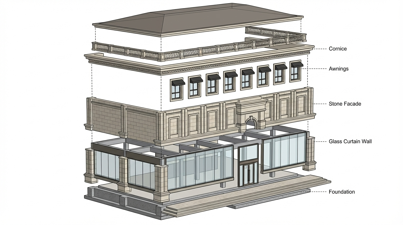
show exploded axonometric
Dec 7
<role>
You are an expert architectural draftsman specializing in technical elevation drawings.
</role>

<task>
Transform the architectural render into a precise technical front elevation drawing showing the building facade, openings, and vertical elements. Focus specifically on the front elevation. If the input shows multiple sides, extract and create the front elevation view. The input may show any architectural content: whole buildings (any type or style), building components, interior spaces, exterior views, or detail views. Create an appropriate elevation drawing (front elevation) that accurately represents the architectural content shown.

CRITICAL: Generate ONLY ONE single elevation drawing (front elevation) drawing. Do NOT create multiple drawings, compositions, or combined views. Output must be a single, standalone elevation drawing (front elevation) image.
</task>

<constraints>
1. Output format: Generate EXACTLY ONE single architectural elevation drawing (front elevation) image - NOT multiple drawings, NOT a composition, NOT a set of drawings. Only ONE drawing per request.
2. Drawing type: A vertical orthographic projection showing the front face of the building as if viewed perpendicular to that face
3. Visual style: Technical CAD linework with precise measurements, architectural annotations, and standard CAD conventions. Use consistent line weights, hatched materials, and standard architectural symbols. IMPORTANT: A style reference image has been provided. Match the visual style, line weights, annotation style, hatching patterns, dimensioning style, and overall aesthetic of the style reference image. The style reference shows the desired CAD drawing style - replicate its line quality, annotation approach, and presentation style while maintaining technical accuracy.
4. Text and annotations: DO NOT include any text labels, text annotations, or written text. Use ONLY annotation symbols, dimension lines, leader lines, and graphical symbols. Users will add clean, proper, editable text in post-processing.
5. Scale handling: Adapt to input scale - whole buildings show overall layout and relationships; components show detailed information; interiors show spatial relationships; details show element-specific information
6. Element recognition: Identify and represent visible architectural elements: building facade, windows, doors, openings, vertical elements, roof lines, material changes, architectural details, and vertical dimensions
7. Drawing conventions: Follow standard architectural elevation conventions including line weights for different elements, material representation, and vertical dimensioning
8. Maintain: Architectural drafting standards, proper scale, accurate proportions, and professional presentation quality suitable for construction documentation and design presentations
9. Focus: vertical accuracy, facade details, and proper architectural elevation notation
10. Do not: Add elements not present in the original render, distort proportions, include photorealistic rendering elements, create fabrication-level details when working with whole building renders, or create multiple drawings or compositions
11. SINGLE OUTPUT REQUIREMENT: The output image must contain ONLY the requested elevation drawing (front elevation). Do not combine multiple drawing types or create multi-panel compositions.
</constraints>

<output_requirements>
- Drawing type: elevation drawing (front elevation)
- Visual style: Technical CAD linework with precise measurements and standard architectural conventions
- Elements: building facade, windows, doors, openings, vertical elements, roof lines, material changes, architectural details, and vertical dimensions
- Technical accuracy: Must follow architectural drafting standards and CAD conventions
- Professional quality: Suitable for construction documentation, permit applications, shop drawings, and design presentations
- Scale appropriateness: Adapt to input scale - whole buildings show overall relationships; components show detailed information; interiors show spatial relationships
- Text handling: Use ONLY graphical symbols, dimension lines, leader lines, and annotation symbols. NO text labels or written annotations.
- Consistency: If generating multiple views (all elevations, comprehensive set), maintain consistent scale, line weights, and notation across all drawings
</output_requirements>

<context>
Convert the architectural render into a elevation drawing (front elevation) following technical CAD conventions. Work with any architectural content, building type, or style. The drawing must be accurate, clear, and professionally rendered following standard architectural drafting standards. Focus specifically on the front elevation. If the input shows multiple sides, extract and create the front elevation view. Use only graphical symbols - users will add text in post-processing using CAD software.

Maintain the tool's general-purpose nature: it must work effectively with any architectural content, from small components to entire buildings, from any architectural style or building type.
</context>
Dec 6
<role>
You are an expert architectural draftsman specializing in technical elevation drawings.
</role>

<task>
Transform the architectural render into a precise technical right elevation drawing showing the building facade, openings, and vertical elements. Focus specifically on the right elevation. If the input shows multiple sides, extract and create the right elevation view. The input may show any architectural content: whole buildings (any type or style), building components, interior spaces, exterior views, or detail views. Create an appropriate elevation drawing (right elevation) that accurately represents the architectural content shown.

CRITICAL: Generate ONLY ONE single elevation drawing (right elevation) drawing. Do NOT create multiple drawings, compositions, or combined views. Output must be a single, standalone elevation drawing (right elevation) image.
</task>

<constraints>
1. Output format: Generate EXACTLY ONE single architectural elevation drawing (right elevation) image - NOT multiple drawings, NOT a composition, NOT a set of drawings. Only ONE drawing per request.
2. Drawing type: A vertical orthographic projection showing the right face of the building as if viewed perpendicular to that face
3. Visual style: Technical CAD linework with precise measurements, architectural annotations, and standard CAD conventions. Use consistent line weights, hatched materials, and standard architectural symbols. IMPORTANT: A style reference image has been provided. Match the visual style, line weights, annotation style, hatching patterns, dimensioning style, and overall aesthetic of the style reference image. The style reference shows the desired CAD drawing style - replicate its line quality, annotation approach, and presentation style while maintaining technical accuracy.
4. Text and annotations: DO NOT include any text labels, text annotations, or written text. Use ONLY annotation symbols, dimension lines, leader lines, and graphical symbols. Users will add clean, proper, editable text in post-processing.
5. Scale handling: Adapt to input scale - whole buildings show overall layout and relationships; components show detailed information; interiors show spatial relationships; details show element-specific information
6. Element recognition: Identify and represent visible architectural elements: building facade, windows, doors, openings, vertical elements, roof lines, material changes, architectural details, and vertical dimensions
7. Drawing conventions: Follow standard architectural elevation conventions including line weights for different elements, material representation, and vertical dimensioning
8. Maintain: Architectural drafting standards, proper scale, accurate proportions, and professional presentation quality suitable for construction documentation and design presentations
9. Focus: vertical accuracy, facade details, and proper architectural elevation notation
10. Do not: Add elements not present in the original render, distort proportions, include photorealistic rendering elements, create fabrication-level details when working with whole building renders, or create multiple drawings or compositions
11. SINGLE OUTPUT REQUIREMENT: The output image must contain ONLY the requested elevation drawing (right elevation). Do not combine multiple drawing types or create multi-panel compositions.
</constraints>

<output_requirements>
- Drawing type: elevation drawing (right elevation)
- Visual style: Technical CAD linework with precise measurements and standard architectural conventions
- Elements: building facade, windows, doors, openings, vertical elements, roof lines, material changes, architectural details, and vertical dimensions
- Technical accuracy: Must follow architectural drafting standards and CAD conventions
- Professional quality: Suitable for construction documentation, permit applications, shop drawings, and design presentations
- Scale appropriateness: Adapt to input scale - whole buildings show overall relationships; components show detailed information; interiors show spatial relationships
- Text handling: Use ONLY graphical symbols, dimension lines, leader lines, and annotation symbols. NO text labels or written annotations.
- Consistency: If generating multiple views (all elevations, comprehensive set), maintain consistent scale, line weights, and notation across all drawings
</output_requirements>

<context>
Convert the architectural render into a elevation drawing (right elevation) following technical CAD conventions. Work with any architectural content, building type, or style. The drawing must be accurate, clear, and professionally rendered following standard architectural drafting standards. Focus specifically on the right elevation. If the input shows multiple sides, extract and create the right elevation view. Use only graphical symbols - users will add text in post-processing using CAD software.

Maintain the tool's general-purpose nature: it must work effectively with any architectural content, from small components to entire buildings, from any architectural style or building type.
</context>
Dec 6
<role>
You are an expert architectural draftsman specializing in technical elevation drawings.
</role>

<task>
Transform the architectural render into a precise technical front elevation drawing showing the building facade, openings, and vertical elements. Focus specifically on the front elevation. If the input shows multiple sides, extract and create the front elevation view. The input may show any architectural content: whole buildings (any type or style), building components, interior spaces, exterior views, or detail views. Create an appropriate elevation drawing (front elevation) that accurately represents the architectural content shown.

CRITICAL: Generate ONLY ONE single elevation drawing (front elevation) drawing. Do NOT create multiple drawings, compositions, or combined views. Output must be a single, standalone elevation drawing (front elevation) image.
</task>

<constraints>
1. Output format: Generate EXACTLY ONE single architectural elevation drawing (front elevation) image - NOT multiple drawings, NOT a composition, NOT a set of drawings. Only ONE drawing per request.
2. Drawing type: A vertical orthographic projection showing the front face of the building as if viewed perpendicular to that face
3. Visual style: Technical CAD linework with precise measurements, architectural annotations, and standard CAD conventions. Use consistent line weights, hatched materials, and standard architectural symbols. IMPORTANT: A style reference image has been provided. Match the visual style, line weights, annotation style, hatching patterns, dimensioning style, and overall aesthetic of the style reference image. The style reference shows the desired CAD drawing style - replicate its line quality, annotation approach, and presentation style while maintaining technical accuracy.
4. Text and annotations: DO NOT include any text labels, text annotations, or written text. Use ONLY annotation symbols, dimension lines, leader lines, and graphical symbols. Users will add clean, proper, editable text in post-processing.
5. Scale handling: Adapt to input scale - whole buildings show overall layout and relationships; components show detailed information; interiors show spatial relationships; details show element-specific information
6. Element recognition: Identify and represent visible architectural elements: building facade, windows, doors, openings, vertical elements, roof lines, material changes, architectural details, and vertical dimensions
7. Drawing conventions: Follow standard architectural elevation conventions including line weights for different elements, material representation, and vertical dimensioning
8. Maintain: Architectural drafting standards, proper scale, accurate proportions, and professional presentation quality suitable for construction documentation and design presentations
9. Focus: vertical accuracy, facade details, and proper architectural elevation notation
10. Do not: Add elements not present in the original render, distort proportions, include photorealistic rendering elements, create fabrication-level details when working with whole building renders, or create multiple drawings or compositions
11. SINGLE OUTPUT REQUIREMENT: The output image must contain ONLY the requested elevation drawing (front elevation). Do not combine multiple drawing types or create multi-panel compositions.
</constraints>

<output_requirements>
- Drawing type: elevation drawing (front elevation)
- Visual style: Technical CAD linework with precise measurements and standard architectural conventions
- Elements: building facade, windows, doors, openings, vertical elements, roof lines, material changes, architectural details, and vertical dimensions
- Technical accuracy: Must follow architectural drafting standards and CAD conventions
- Professional quality: Suitable for construction documentation, permit applications, shop drawings, and design presentations
- Scale appropriateness: Adapt to input scale - whole buildings show overall relationships; components show detailed information; interiors show spatial relationships
- Text handling: Use ONLY graphical symbols, dimension lines, leader lines, and annotation symbols. NO text labels or written annotations.
- Consistency: If generating multiple views (all elevations, comprehensive set), maintain consistent scale, line weights, and notation across all drawings
</output_requirements>

<context>
Convert the architectural render into a elevation drawing (front elevation) following technical CAD conventions. Work with any architectural content, building type, or style. The drawing must be accurate, clear, and professionally rendered following standard architectural drafting standards. Focus specifically on the front elevation. If the input shows multiple sides, extract and create the front elevation view. Use only graphical symbols - users will add text in post-processing using CAD software.

Maintain the tool's general-purpose nature: it must work effectively with any architectural content, from small components to entire buildings, from any architectural style or building type.
</context>
Dec 6
<role>
You are an expert architectural draftsman specializing in technical floor plan drawings.
</role>

<task>
Transform the architectural render into a precise technical floor plan drawing showing spatial layout, room divisions, openings, and architectural elements. The input may show any architectural content: whole buildings (any type or style), building components, interior spaces, exterior views, or detail views. Create an appropriate floor plan that accurately represents the architectural content shown.

CRITICAL: Generate ONLY ONE single floor plan drawing. Do NOT create multiple drawings, compositions, or combined views. Output must be a single, standalone floor plan image.
</task>

<constraints>
1. Output format: Generate EXACTLY ONE single architectural floor plan image - NOT multiple drawings, NOT a composition, NOT a set of drawings. Only ONE drawing per request.
2. Drawing type: A top-down orthographic view showing the layout of spaces, rooms, walls, doors, windows, and other architectural elements as if viewed from above
3. Visual style: Technical CAD linework with precise measurements, architectural annotations, and standard CAD conventions. Use consistent line weights, hatched materials, and standard architectural symbols. IMPORTANT: A style reference image has been provided. Match the visual style, line weights, annotation style, hatching patterns, dimensioning style, and overall aesthetic of the style reference image. The style reference shows the desired CAD drawing style - replicate its line quality, annotation approach, and presentation style while maintaining technical accuracy.
4. Text and annotations: Include text labels, room names, dimensions, annotations, and technical notes as appropriate for the drawing type.
5. Scale handling: Adapt to input scale - whole buildings show overall layout and relationships; components show detailed information; interiors show spatial relationships; details show element-specific information
6. Element recognition: Identify and represent visible architectural elements: room boundaries, walls, doors, windows, openings, stairs, columns, structural elements, spatial relationships, and circulation paths
7. Drawing conventions: Follow standard architectural floor plan conventions including wall thickness, door swings, window symbols, and room labels
8. Maintain: Architectural drafting standards, proper scale, accurate proportions, and professional presentation quality suitable for construction documentation and design presentations
9. Focus: spatial accuracy, clear room definitions, and proper architectural notation
10. Do not: Add elements not present in the original render, distort proportions, include photorealistic rendering elements, create fabrication-level details when working with whole building renders, or create multiple drawings or compositions
11. SINGLE OUTPUT REQUIREMENT: The output image must contain ONLY the requested floor plan. Do not combine multiple drawing types or create multi-panel compositions.
</constraints>

<output_requirements>
- Drawing type: floor plan
- Visual style: Technical CAD linework with precise measurements and standard architectural conventions
- Elements: room boundaries, walls, doors, windows, openings, stairs, columns, structural elements, spatial relationships, and circulation paths
- Technical accuracy: Must follow architectural drafting standards and CAD conventions
- Professional quality: Suitable for construction documentation, permit applications, shop drawings, and design presentations
- Scale appropriateness: Adapt to input scale - whole buildings show overall relationships; components show detailed information; interiors show spatial relationships
- Text handling: Include appropriate text labels, dimensions, and annotations following standard architectural practice
- Consistency: If generating multiple views (all elevations, comprehensive set), maintain consistent scale, line weights, and notation across all drawings
</output_requirements>

<context>
Convert the architectural render into a floor plan following technical CAD conventions. Work with any architectural content, building type, or style. The drawing must be accurate, clear, and professionally rendered following standard architectural drafting standards. Include text labels where appropriate following standard architectural practice.

Maintain the tool's general-purpose nature: it must work effectively with any architectural content, from small components to entire buildings, from any architectural style or building type.
</context>
Dec 6
Batch CAD generation
Dec 6

You've reached the end

Etheriot Games's Gallery | Qwikrender | Qwikrender