casso yin
0
Prompt
A removable fabric cover for a product, keep the same shape and proportions。Solid color, no pattern,Polyester fabric with a smooth, tightly woven surface, NO plush, NO fur, NO fuzzy texture, similar to sofa fabric or cushion cover fabric
realisticstandard16:9

More like this
Create a 6-second transformation video using the uploaded bare office site photo as the starting point. Keep the same camera, perspective and structure. Elements appear in clean pop-in stages:
1) Wall finishes switch in to full-height soft green acoustic drapes matching the final interior reference.
2) The entire flooring changes to a smooth polished concrete finish.
3) Workstations pop in group-wise—first the long desk rows, then office chairs, then planters and accessories.
4) The patterned geometric acoustic ceiling panels and wavy green baffles drop in last to complete the space.
Soft bright daylight, minimal clean animation style, fast but smooth transitions, photorealistic, no people, no text, no logos.
🎬 Video
Dec 4
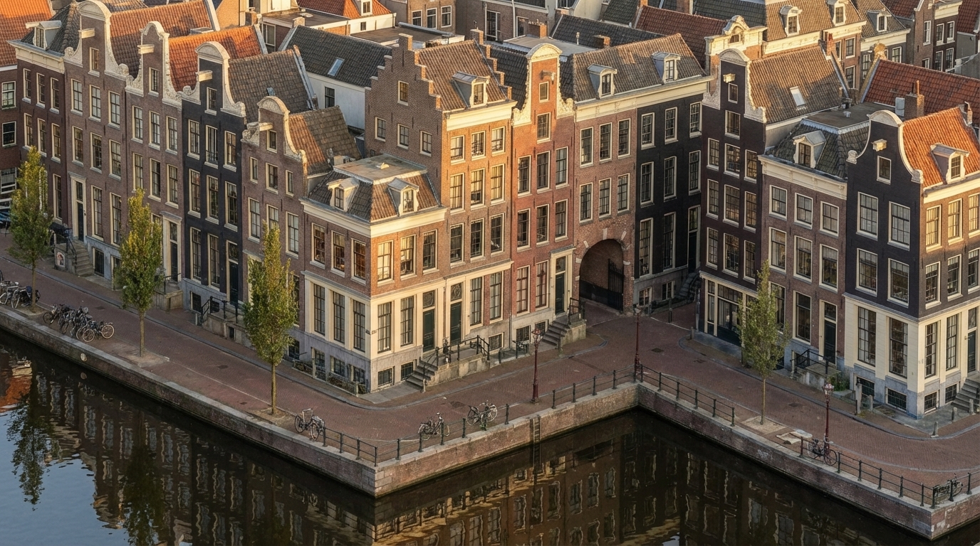
Convert this exact Revit massing into a fully detailed Amsterdam canal-house façade without changing any geometry. Keep the same isometric camera angle exactly as the original view. Apply seventeenth-century Dutch architectural style onto every block by dividing the long façade into narrow vertical bays inspired by real canal houses. Use authentic warm Dutch brick (brown, muted red, dark charcoal) with cream stone trim along corners, edges, and window frames. Add tall vertical windows with thin black mullions, and place stepped, bell, and neck gables only above the existing roof shapes. Convert all plain surfaces into rich brick textures, add cornices at massing offsets, and use recesses as historic alley-like details. Apply a subtle forward tilt (2–3°) to each bay visually, without editing the volumes.
Place a calm reflective canal in front of the full building length, with stone edges, metal railings, bikes, and slim Amsterdam street trees. Use warm golden-hour sunlight with soft reflections on windows and clear isometric reflections in the water. Render in ultra-photorealistic style with crisp textures, natural shadows, warm colors, HDR lighting, and slight filmic imperfections.
Negative prompt: no geometry edits, no modern curtain walls, no futuristic elements, no fisheye, no wrong gables, no unrealistic colors.
Dec 2
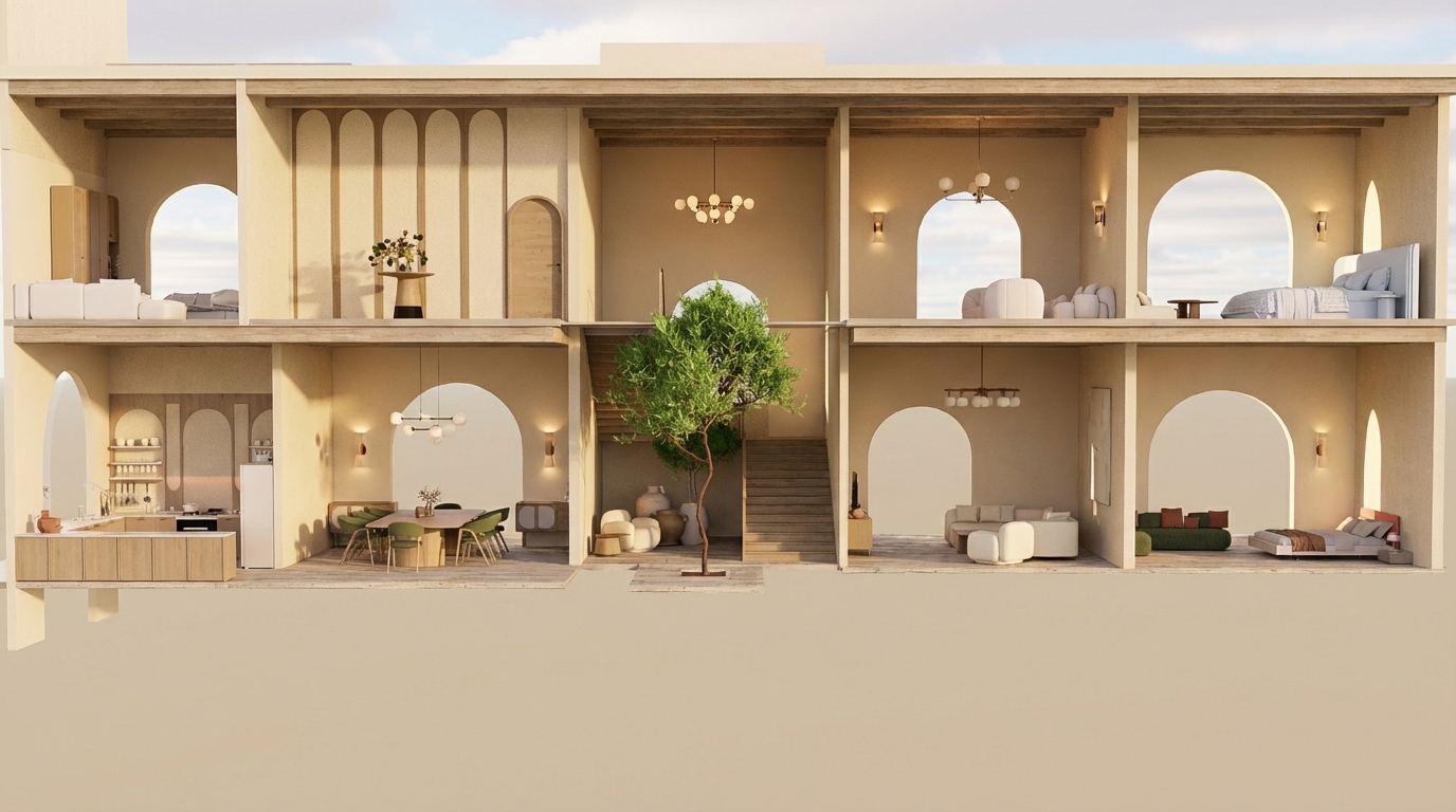
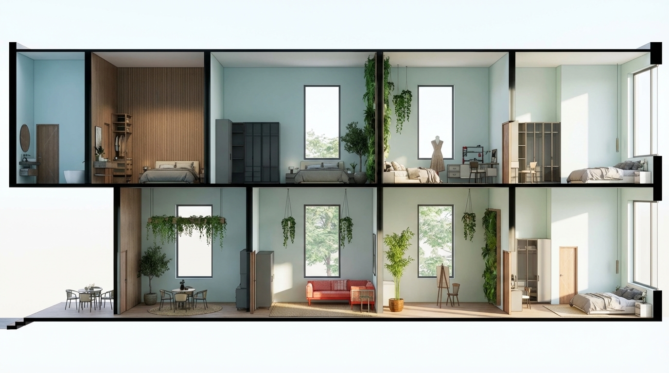
"Create an ultra-realistic render of this two-story Mediterranean-style villa section exactly as shown, keeping all room functions and all furniture placements unchanged.
All walls throughout both floors must be in beige tones only (warm Mediterranean beige).
GROUND FLOOR:
– Left side: open kitchen with upper and lower cabinets; dining area beside it.
– Middle: small seating area before the staircase; indoor vertical patio with a tree extending through both levels.
– Right side: main living room; and directly next to it a bedroom exactly as shown.
FIRST FLOOR:
– Left: bedroom; next to it a decorative gallery space with arched wall panels and a console table.
– Middle: double-height void above the indoor tree and staircase landing.
– Right: small sitting area; and at the far right a bedroom with arched opening.
Architectural requirements: preserve arches, openings, proportions, and room layout exactly as shown.
Rendering instructions:
– Do NOT change or modify any furniture; keep the exact furniture pieces and positions.
– All walls must be beige.
– Use modern lighting fixtures with warm Mediterranean ambiance.
– Use light-colored wood (not dark) for all wooden elements.
– Add highly detailed textures, refined materials, micro-details, realistic reflections, volumetric light, soft shadows, and a warm Mediterranean atmosphere.
– Maintain Mediterranean color palette: beige, warm brown, olive, deep burnt orange.
– Add elegant Mediterranean-style chandeliers without altering furniture layout
Dec 2

Cinematic architectural enhancement of an existing container house. Add realistic landscaping around the structure, including tall ornamental grasses, low shrubs, small bushes, and a few medium-height trees surrounding the site. Place a concrete platform base with a subtle step-up entrance. Add a narrow stone pathway and a clean asphalt road in the foreground. Install modern minimal bollard lights along the road and walkway. Add warm exterior wall lights on the facade to create a cozy glow. Enhance natural sunlight to golden hour, with soft shadows, warm tones, and realistic reflections on the glass windows. Add distant mountains, open field, and trees in the background under a slightly cloudy sky. Make the scene modern, calm, eco-friendly, and photorealistic.
Render style: Ultra-realistic, cinematic, 4K, depth of field, soft shadows, HDR lighting, realistic textures, professional architectural visualization. “Keep the original structure unchanged. Only enhance environment, lighting, plants, and atmosphere.”
Dec 2
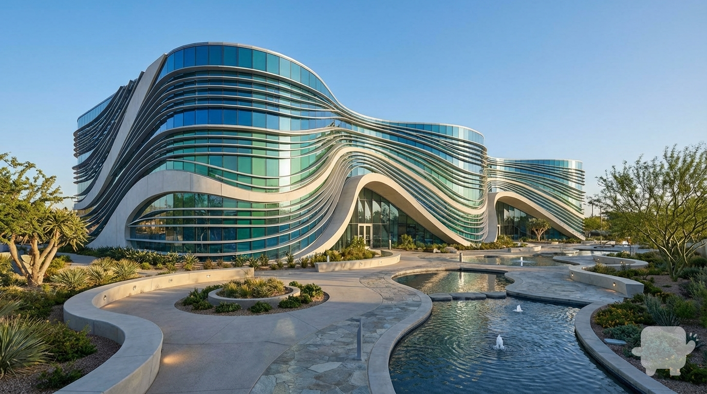
I am providing a basic 3D mass model of a building with no design details.
Please develop the architectural form based on a water wave concept, while keeping the original building massing intact.
I need smooth, fluid, dynamic façade lines inspired by the motion of water.
Requirements:
Create façade articulation inspired by water waves.
Add openings, shading elements, curves, or structural fins supporting the wave concept.
Use modern materials such as glass, aluminum, and GFRC.
Design a complete landscape for the site, including curved pathways, planting areas, ground lighting, and subtle water-themed elements.
Produce a high-quality final realistic render."
Dec 8
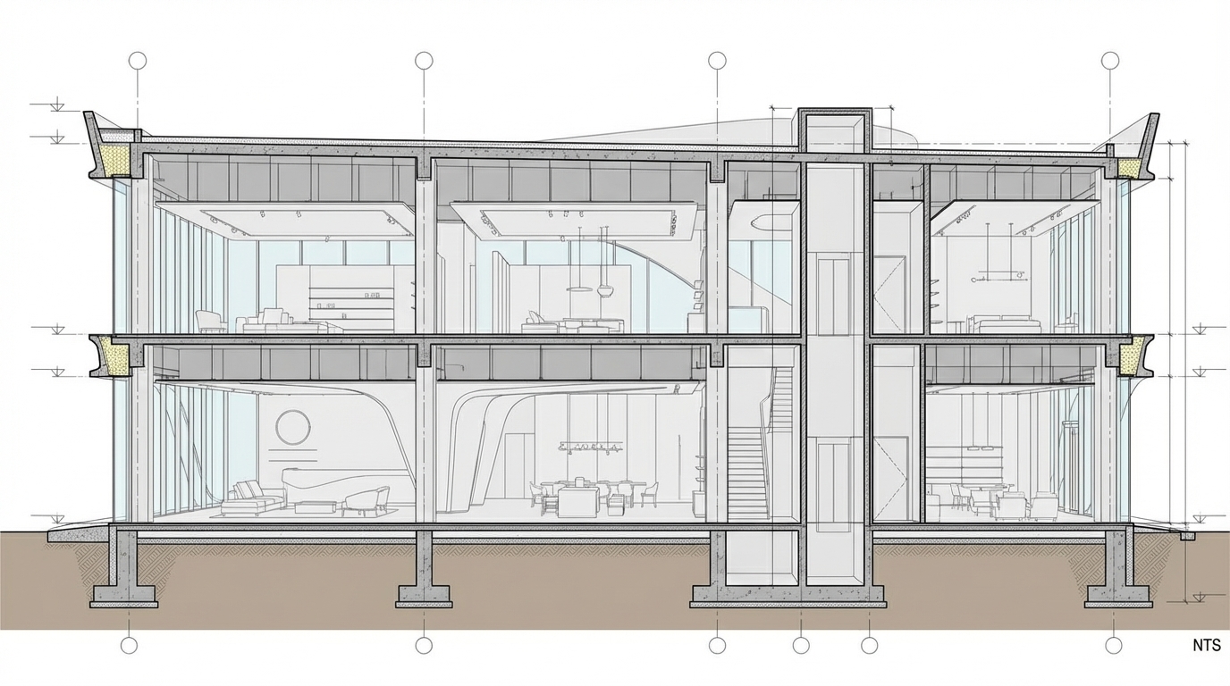
High-quality interior architectural section render, keeping all existing furniture exactly the same and in the same positions. Apply a soft biophilic design style with natural elements such as indoor plants, organic textures, and subtle greenery integration. Walls finished in a gentle breeze-color tone (light, airy, pastel cool-tone). Add clean, modern windows that enhance daylight penetration without altering the layout. Maintain the original spatial proportions, materials of furniture, and all architectural lines. Realistic lighting, soft natural light, high detail, photorealistic style, sharp linework, premium interior visualization, 4K
Dec 2
“Turn this architectural still image into a smooth cinematic animation. Keep the design, materials, colors, and proportions exactly the same. Add realistic daylight, subtle camera motion, natural shadows, and soft environmental effects. No distortion, no style change, no redesign — only a clean and realistic animation of the original image
Dec 8
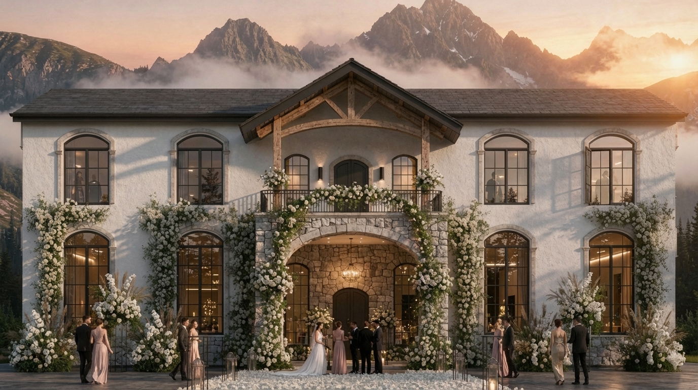
Generate A highly realistic, photorealistic render of the exact same two-story Mediterranean / modern-classic wedding venue shown. Keep the building identical in shape, massing, proportions, roof, windows, façade, and all architectural elements. Maintain the same white textured stucco, arched black windows, stone trims, and full floral installations climbing along the façade. Enhance realism with natural sunrise lighting, soft shadows, volumetric atmosphere, sharp material texturing, and accurate reflections in the glass. Modify only the heavy timber truss above the balcony: keep its structure the same, but make the bottom chord gently curved to aesthetically match the arches on the façade, while keeping all other truss members unchanged. Add a few elegant, well-dressed wedding guests walking or standing near the entrance to give realistic scale and liveliness, ensuring they look natural and not staged. Keep the mountain background, fog, floral arrangements, and overall composition exactly the same. Ultra-realistic 8K render, global illumination, depth of field, crisp shadows, physically accurate lighting.
Dec 2
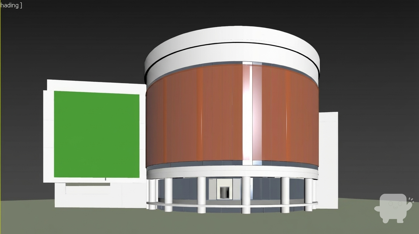
I NEED YOU TO KEEP THE DESIGN AS IS EXACTLY IN THE RAW IMAGE WITH NO LOUVERS AND MAKE THE GREEN WALL BIGGERFOLLOW THE UPLOADED RAW IMAGE NOW AS IS IN DESIGN NOW CHANGE IN DESIGN
Dec 6
Generate A highly realistic, photorealistic render of the exact same two-story Mediterranean / modern-classic wedding venue shown. Keep the building identical in shape, massing, proportions, roof, windows, façade, and all architectural elements. Maintain the same white textured stucco, arched black windows, stone trims, and full floral installations climbing along the façade. Enhance realism with natural sunrise lighting, soft shadows, volumetric atmosphere, sharp material texturing, and accurate reflections in the glass. Modify only the heavy timber truss above the balcony: keep its structure the same, but make the bottom chord gently curved to aesthetically match the arches on the façade, while keeping all other truss members unchanged. Add a few elegant, well-dressed wedding guests walking or standing near the entrance to give realistic scale and liveliness, ensuring they look natural and not staged. Keep the mountain background, fog, floral arrangements, and overall composition exactly the same. Ultra-realistic 8K render, global illumination, depth of field, crisp shadows, physically accurate lighting.
Dec 2