Eva Abdullah
0
More like this
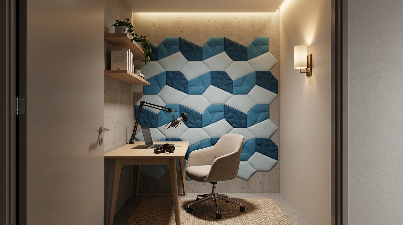
Compact focus room designed for video calls and podcasting, PET acoustic wall panels in soft muted colours behind the desk, small worktable with microphone, comfortable chair and simple shelves, warm ambient lighting with a wall sconce and hidden LED strip, cozy modern interior with matte finishes, no clutter, seen from the doorway at eye level, photorealistic architectural render, high detail, soft shadows, professional interior visualization quality, no people, no text, no logos.
Dec 4
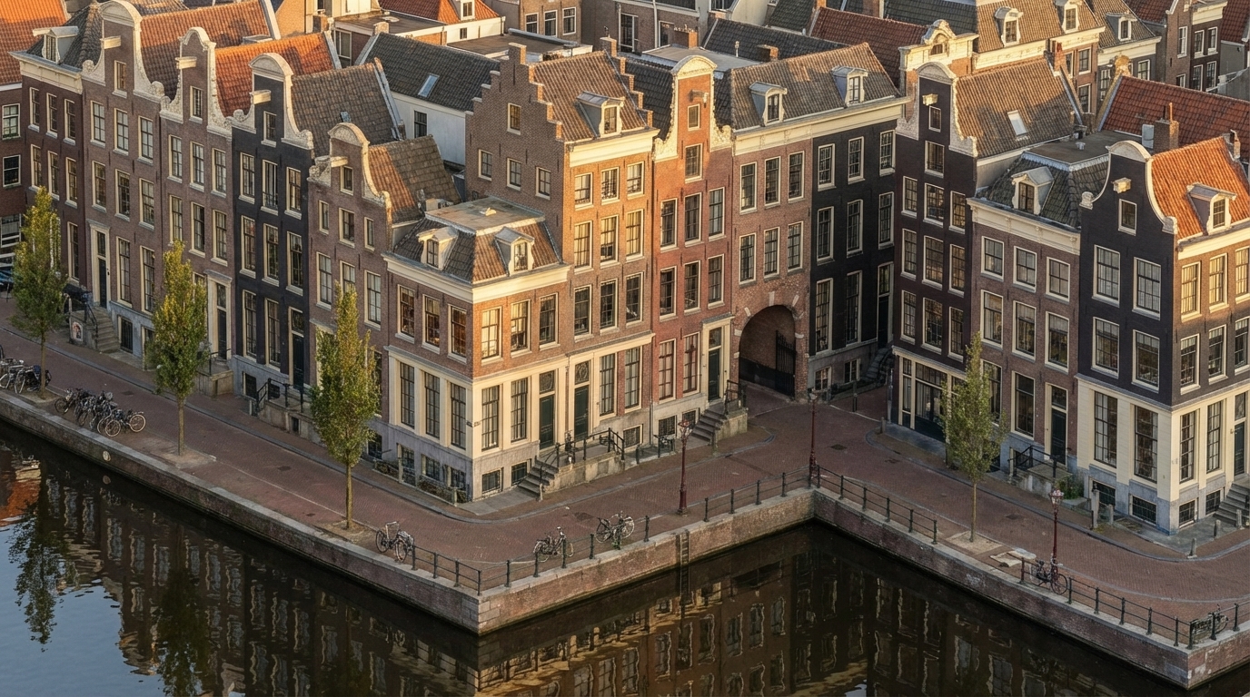
Convert this exact Revit massing into a fully detailed Amsterdam canal-house façade without changing any geometry. Keep the same isometric camera angle exactly as the original view. Apply seventeenth-century Dutch architectural style onto every block by dividing the long façade into narrow vertical bays inspired by real canal houses. Use authentic warm Dutch brick (brown, muted red, dark charcoal) with cream stone trim along corners, edges, and window frames. Add tall vertical windows with thin black mullions, and place stepped, bell, and neck gables only above the existing roof shapes. Convert all plain surfaces into rich brick textures, add cornices at massing offsets, and use recesses as historic alley-like details. Apply a subtle forward tilt (2–3°) to each bay visually, without editing the volumes.
Place a calm reflective canal in front of the full building length, with stone edges, metal railings, bikes, and slim Amsterdam street trees. Use warm golden-hour sunlight with soft reflections on windows and clear isometric reflections in the water. Render in ultra-photorealistic style with crisp textures, natural shadows, warm colors, HDR lighting, and slight filmic imperfections.
Negative prompt: no geometry edits, no modern curtain walls, no futuristic elements, no fisheye, no wrong gables, no unrealistic colors.
Dec 2
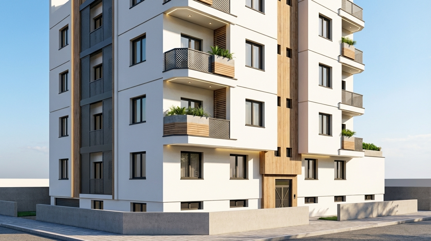
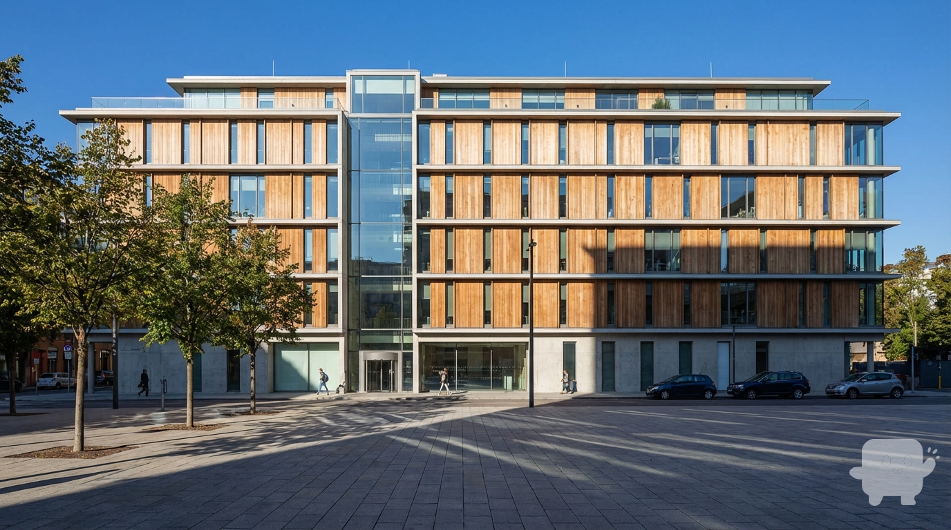
Façade contemporaine minimaliste : volumes géométriques simples, enduit blanc, bois naturel, métal perforé et vitrages à cadres fins noirs. Rythme vertical et horizontal subtil pour alléger le volume. Intégration de brise-soleil, jardinières modernes et éclairage architectural. Style moderne, sobre, harmonieux et photoréaliste.
Dec 2
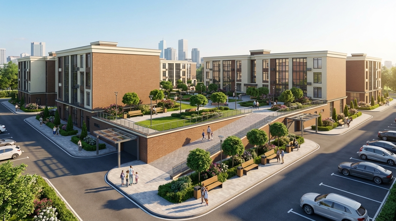
Render this residential complex exactly as designed, without altering its architecture, proportions, colors, façade materials, or geometry, including window sizes, shapes, and volumes.
Enhance the scene to be realistic, modern, and high-quality. Create a second-level courtyard located in the center of the residential complex, not outside the buildings. Include wide sidewalks, pedestrian walkways, benches, street lamps, trash bins, and decorative landscaping: green grass, neatly shaped trees, bushes, and flowerbeds, all matching the architectural style.
Add a ramp providing safe access to the second-level courtyard, integrated naturally with the buildings and landscaping. Include clean asphalt roads, organized parking spaces, several modern cars, and a realistic number of people — pedestrians, families, and residents — to create a lively atmosphere.
Add a subtle city skyline or urban background visible behind the complex, without distracting from the courtyard scene. Use soft daylight with realistic shadows and global illumination.
IMPORTANT: Place entrance ramps to the underground parking at the correct height — at the level of the first floor, elevated from the ground, exactly as in the original 3D model. Add modern metal-and-glass canopies above these ramps.
Ensure the final render is highly realistic, elegant, and visually cohesive, while preserving the exact form, geometry, and colors of the buildings.
Dec 2

Cinematic architectural enhancement of an existing container house. Add realistic landscaping around the structure, including tall ornamental grasses, low shrubs, small bushes, and a few medium-height trees surrounding the site. Place a concrete platform base with a subtle step-up entrance. Add a narrow stone pathway and a clean asphalt road in the foreground. Install modern minimal bollard lights along the road and walkway. Add warm exterior wall lights on the facade to create a cozy glow. Enhance natural sunlight to golden hour, with soft shadows, warm tones, and realistic reflections on the glass windows. Add distant mountains, open field, and trees in the background under a slightly cloudy sky. Make the scene modern, calm, eco-friendly, and photorealistic.
Render style: Ultra-realistic, cinematic, 4K, depth of field, soft shadows, HDR lighting, realistic textures, professional architectural visualization. “Keep the original structure unchanged. Only enhance environment, lighting, plants, and atmosphere.”
Dec 2
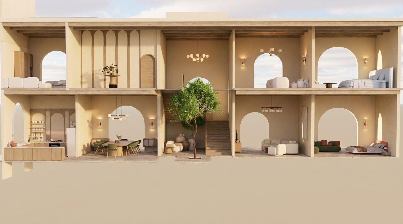
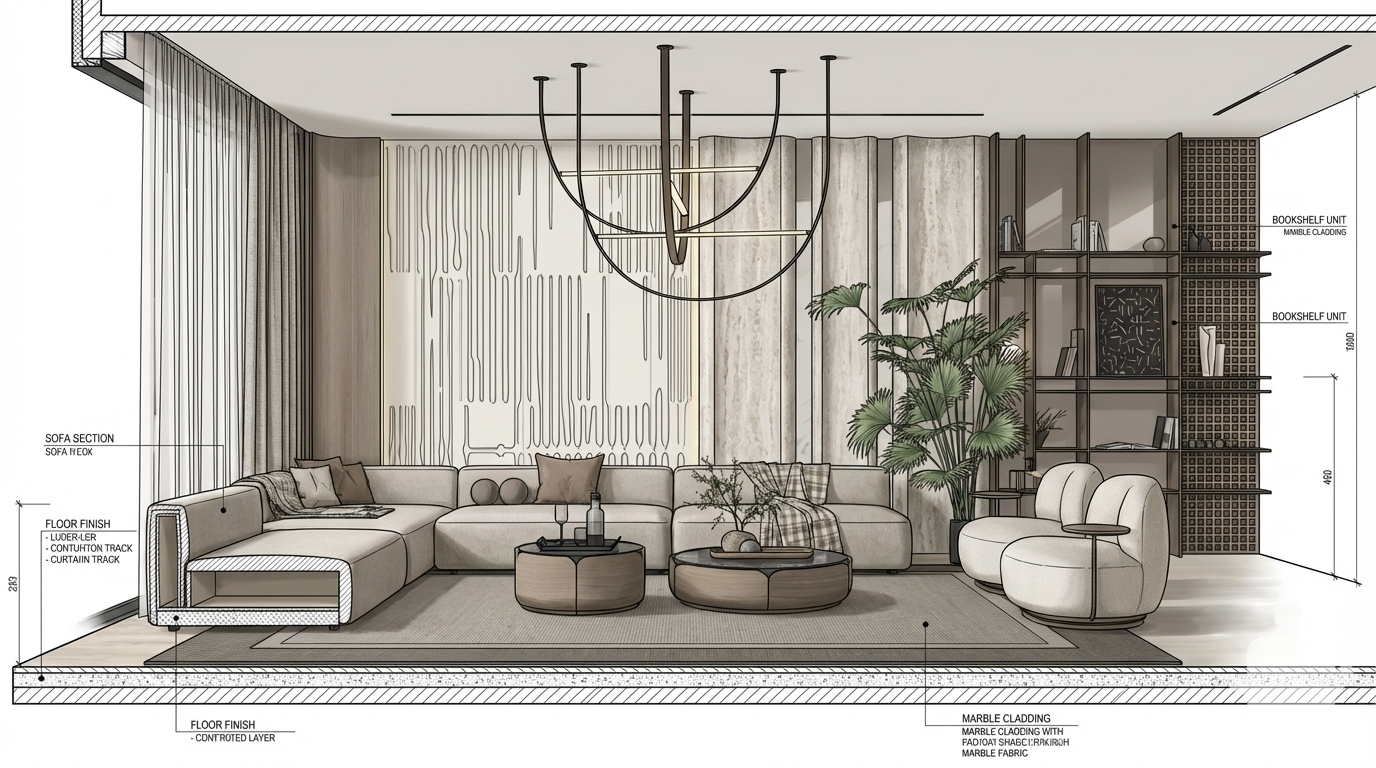
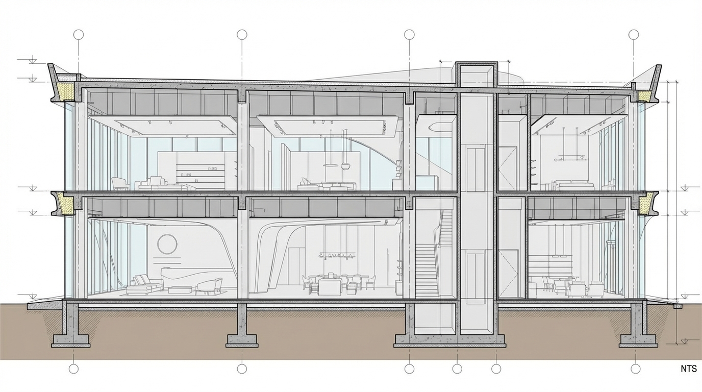
"Create an ultra-realistic render of this two-story Mediterranean-style villa section exactly as shown, keeping all room functions and all furniture placements unchanged.
All walls throughout both floors must be in beige tones only (warm Mediterranean beige).
GROUND FLOOR:
– Left side: open kitchen with upper and lower cabinets; dining area beside it.
– Middle: small seating area before the staircase; indoor vertical patio with a tree extending through both levels.
– Right side: main living room; and directly next to it a bedroom exactly as shown.
FIRST FLOOR:
– Left: bedroom; next to it a decorative gallery space with arched wall panels and a console table.
– Middle: double-height void above the indoor tree and staircase landing.
– Right: small sitting area; and at the far right a bedroom with arched opening.
Architectural requirements: preserve arches, openings, proportions, and room layout exactly as shown.
Rendering instructions:
– Do NOT change or modify any furniture; keep the exact furniture pieces and positions.
– All walls must be beige.
– Use modern lighting fixtures with warm Mediterranean ambiance.
– Use light-colored wood (not dark) for all wooden elements.
– Add highly detailed textures, refined materials, micro-details, realistic reflections, volumetric light, soft shadows, and a warm Mediterranean atmosphere.
– Maintain Mediterranean color palette: beige, warm brown, olive, deep burnt orange.
– Add elegant Mediterranean-style chandeliers without altering furniture layout
Dec 2

Convert this exact Revit building massing into a complete and highly detailed Amsterdam-style architectural façade while strictly preserving every block, setback, height, and proportion of the original geometry. Apply the seventeenth-century Dutch canal house identity directly onto the existing horizontal mass, treating each vertical module, recess, and projection as an individual façade bay. Maintain the building as one continuous structure while visually subdividing it into rhythmically narrow Amsterdam-style segments with stepped, bell, and neck gables applied only above existing rooflines without altering the massing. Use warm brown, muted red, and deep charcoal brick textures combined with cream stone trim outlining corners and window surrounds. Integrate tall vertical windows with thin black mullions, placing decorative cornices at horizontal massing transitions and using recesses as historic alley moments. Convert all solid walls into richly detailed brick façades with traditional Dutch ornamentation, ensuring a subtle two-to-three-degree forward façade tilt for authenticity without modifying geometry.
Place a calm reflective canal directly along the entire front length of the building, adding stone edges, metal railings, bicycles, and slender street trees typical of Amsterdam’s canals. Illuminate the scene with warm golden-hour sunlight at a low angle, producing soft highlights on window glass and warm reflections in the canal. Use a wide-angle twenty-four to twenty-eight millimeter lens at eye level with a straight frontal perspective capturing clear water reflections and gentle ripples. Render the scene with ultra-photorealistic quality, high dynamic range, crisp material textures, natural shadow falloff, warm filmic color grading, and slight chromatic imperfections for historical realism.
Negative prompt: avoid geometry changes, futuristic elements, modern curtain walls, erased volumes, misaligned gables, unrealistic colors, and fisheye distortion. Ensure consistent weathering realistic brick aging subtle mortar variation historically accurate roof edges precise gable alignment natural ambient occlusion and refined reflective highlights across all surfaces for authenticity.
Dec 2

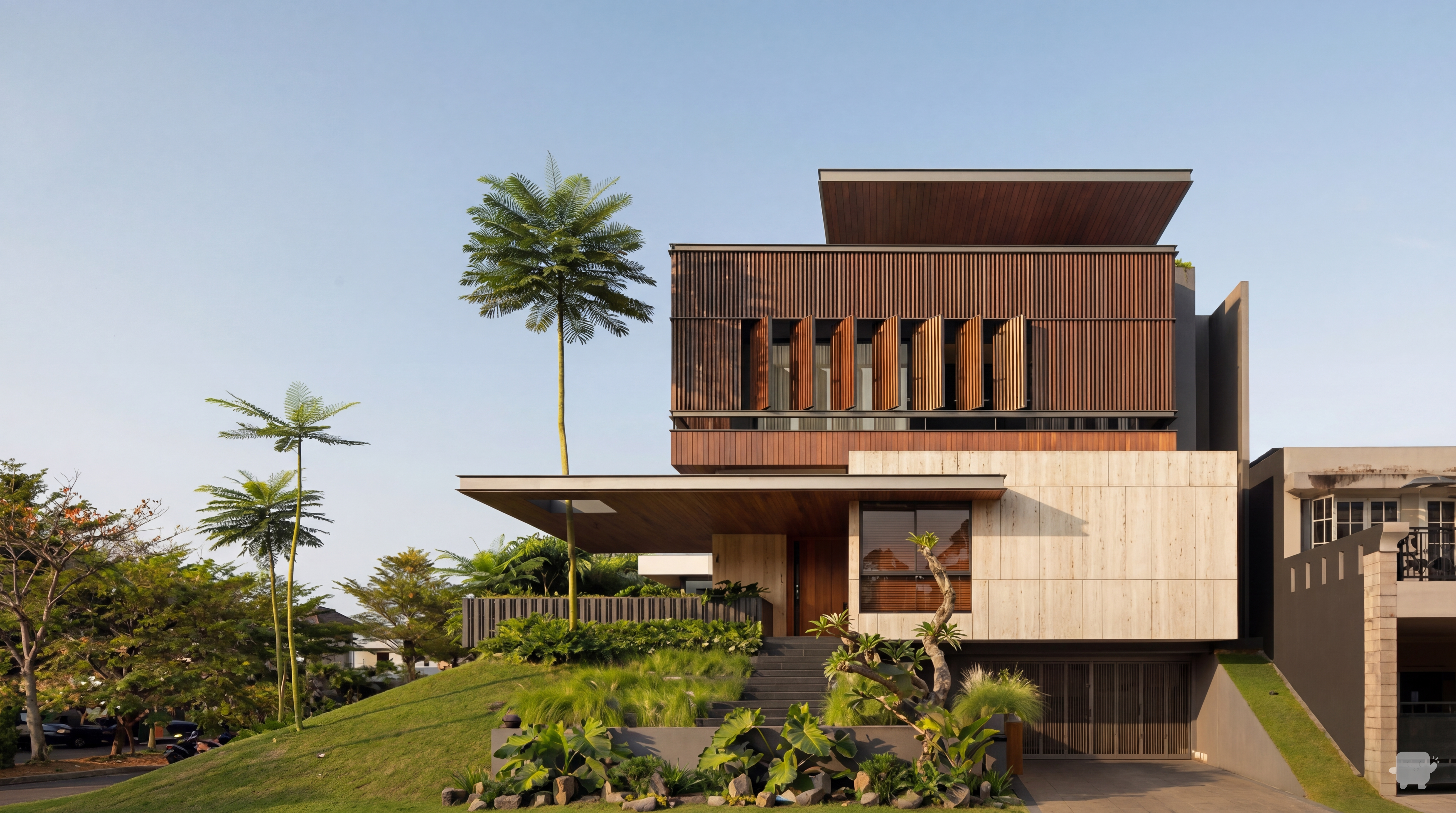
Create a super high-quality photorealistic exterior render of this modern villa from SketchUp/Revit. Preserve building geometry and camera angle. Apply realistic materials (stone, concrete, wood, glass) with accurate reflections. Use soft, natural, volumetric shadows, subtle global illumination, ambient daylight (without direct sun if desired), balanced exterior and interior lighting. Show interior details visible through windows, including chandelier and furniture. Include realistic landscaping and trees. Include subtle people for scale. No cars, no text, no stylization. Professional architectural visualization, cinematic and photorealistic
Dec 17

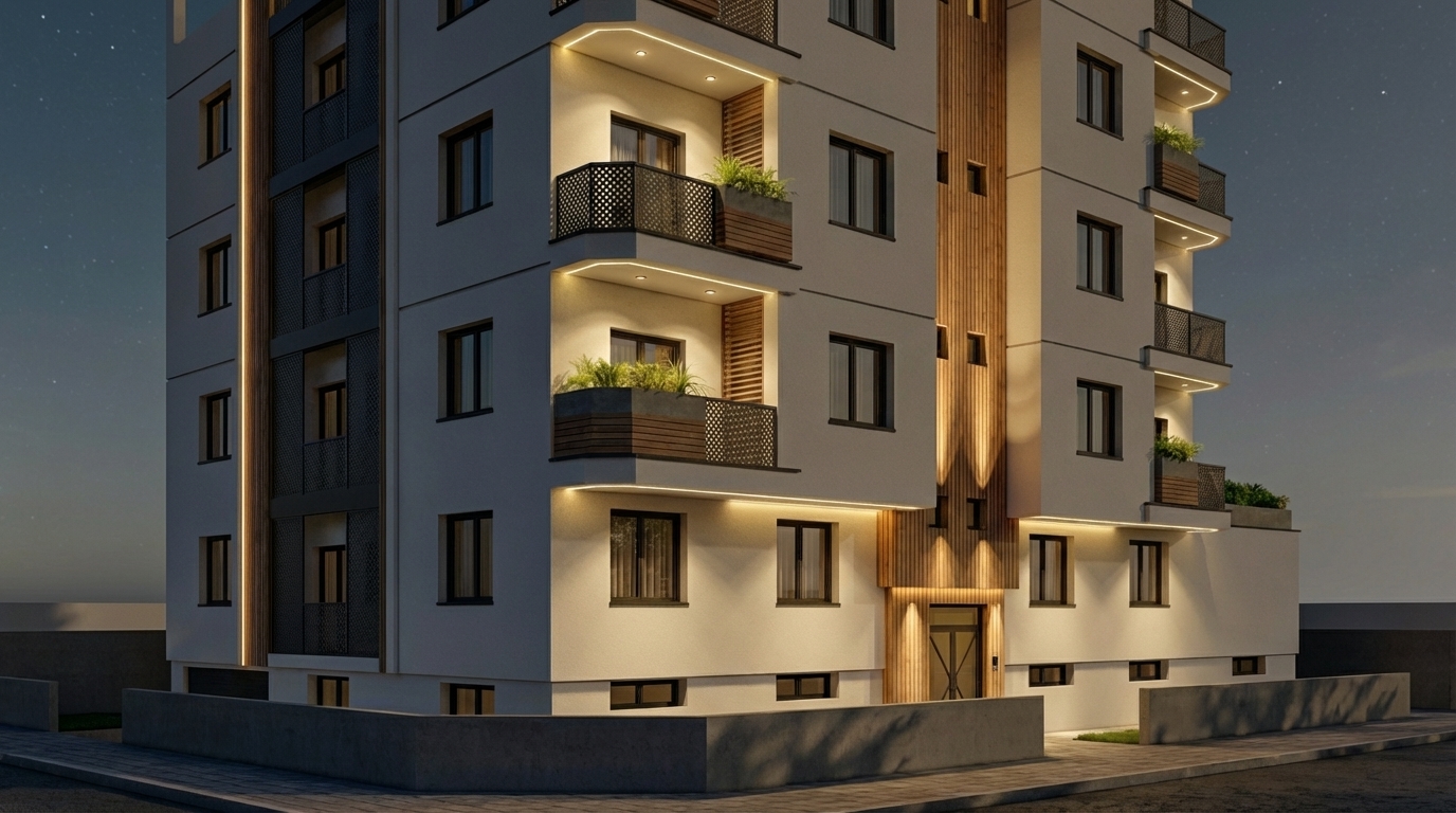
Exterior of a modern house facade in a residential condominium, door with light color, stone cladding not too yellow, LED strip under the higher marquise running down the left side vertically to the ground, subtle warm interior lighting visible through the garage, garage not dark, realistic lighting, soft shadows, high-quality architectural visualization, photorealistic, daytime with soft ambient light, attention to material textures, surrounding residential environment with gentle landscaping, light vegetation and plants to create a natural ambiance, beautiful sky with soft clouds, photorealistic exterior setting
Dec 19
A building exterior view in bright natural daylight, clear blue sky, well-lit facade, natural shadows, surrounding landscape or urban context, photorealistic architectural exterior rendering
Dec 14
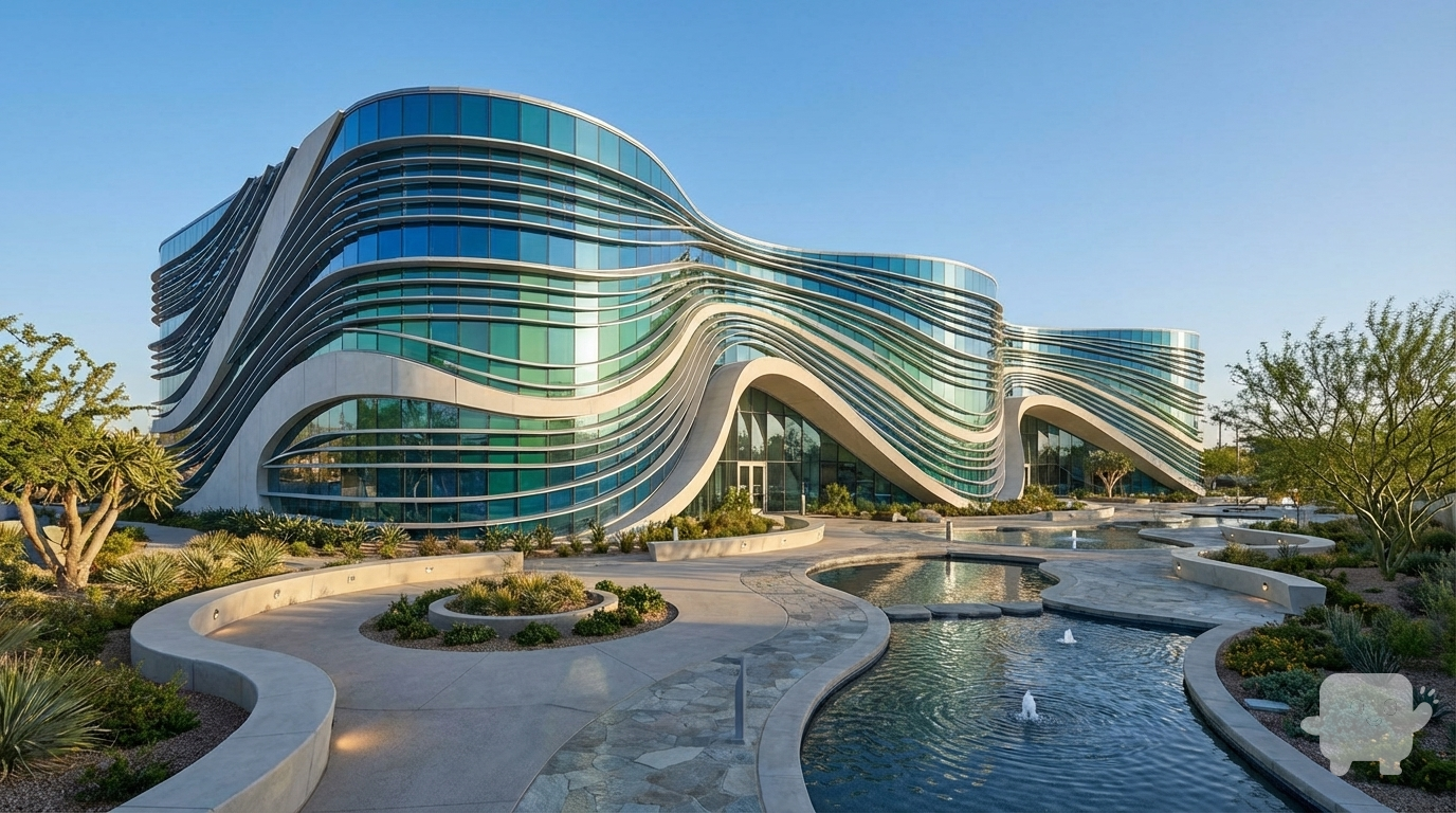
I am providing a basic 3D mass model of a building with no design details.
Please develop the architectural form based on a water wave concept, while keeping the original building massing intact.
I need smooth, fluid, dynamic façade lines inspired by the motion of water.
Requirements:
Create façade articulation inspired by water waves.
Add openings, shading elements, curves, or structural fins supporting the wave concept.
Use modern materials such as glass, aluminum, and GFRC.
Design a complete landscape for the site, including curved pathways, planting areas, ground lighting, and subtle water-themed elements.
Produce a high-quality final realistic render."
Dec 8
Façade architecturale moderne, aux lignes épurées et volumes simples. Utiliser un mélange d’enduit clair (blanc ou beige), de bardage en bois vertical et de pierre naturelle pour créer une ambiance chaleureuse et contemporaine. Grandes baies vitrées avec encadrements fins en aluminium noir. Intégrer des brise-soleil horizontaux pour le contrôle solaire. Ajouter un éclairage LED indirect intégré à la façade pour un rendu élégant de nuit. Matériaux réalistes, textures détaillées, ombres naturelles, rendu photoréaliste et ambiance lumineuse douce.
Dec 2