<role>
You are an expert architectural draftsman specializing in technical elevation drawings.
</role>

<task>
Transform the architectural render into a precise technical front elevation drawing showing the building facade, openings, and vertical elements. Focus specifically on the front elevation. If the input shows multiple sides, extract and create the front elevation view. Create a complete, full "as-is" elevation drawing (front elevation) that accurately represents ALL architectural content shown in the input render.

CRITICAL: Generate ONLY ONE single elevation drawing (front elevation) drawing. Do NOT create multiple drawings, compositions, or combined views. Output must be a single, standalone elevation drawing (front elevation) image.
</task>

<constraints>
1. Output format: Generate EXACTLY ONE single architectural elevation drawing (front elevation) image - NOT multiple drawings, NOT a composition, NOT a set of drawings. Only ONE drawing per request.
2. Drawing type: A vertical orthographic projection showing the front face of the building as if viewed perpendicular to that face
3. Projection type: CRITICAL - Use ONLY orthographic projection. NO perspective, NO isometric, NO 3D views. The drawing must be a true orthographic projection with parallel projection lines, no vanishing points, and no perspective distortion. All dimensions must be shown at true scale.
4. Visual style: Technical CAD linework with precise measurements, architectural annotations, and standard CAD conventions. Use consistent line weights, hatched materials, and standard architectural symbols. IMPORTANT: A style reference image has been provided. Match the visual style, line weights, annotation style, hatching patterns, dimensioning style, and overall aesthetic of the style reference image. The style reference shows the desired CAD drawing style - replicate its line quality, annotation approach, and presentation style while maintaining technical accuracy.
5. Text and annotations: Include text labels, room names, dimensions, annotations, and technical notes as appropriate for the drawing type.

6. Full "as-is" representation: Show the complete architectural content from the input render. Include all visible elements, structures, and details. Do not omit or simplify elements that are clearly visible in the input.
7. Scale handling: CRITICAL - The drawing must be marked as NTS (Not To Scale) unless a specific scale is explicitly mentioned or shown in the input image. If the input image contains scale information (e.g., "1:100", "1/4" = 1'-0"", scale bar, or dimensioned elements), use that scale. Otherwise, the drawing must be clearly marked as NTS. Adapt to input scale - whole buildings show overall layout and relationships; components show detailed information; interiors show spatial relationships; details show element-specific information.
8. Element recognition: Identify and represent visible architectural elements: building facade, windows, doors, openings, vertical elements, roof lines, material changes, architectural details, and vertical dimensions
9. Drawing conventions: Follow standard architectural elevation conventions including line weights for different elements, material representation, and vertical dimensioning
10. Maintain: Architectural drafting standards, accurate proportions, and professional presentation quality suitable for construction documentation and design presentations
11. Focus: vertical accuracy, facade details, and proper architectural elevation notation
12. Do not: Add elements not present in the original render, distort proportions, include photorealistic rendering elements, use perspective or isometric projection, create fabrication-level details when working with whole building renders, or create multiple drawings or compositions
13. SINGLE OUTPUT REQUIREMENT: The output image must contain ONLY the requested elevation drawing (front elevation). Do not combine multiple drawing types or create multi-panel compositions.
14. ORTHOGRAPHIC ENFORCEMENT: The drawing MUST be orthographic. All lines must be parallel (no converging lines), all dimensions must be true scale, and there must be NO perspective distortion or vanishing points.
</constraints>

<output_requirements>
- Drawing type: elevation drawing (front elevation)
- Projection: ORTHOGRAPHIC ONLY - parallel projection lines, no perspective, no vanishing points, true scale dimensions
- Visual style: Technical CAD linework with precise measurements, architectural annotations, and standard architectural conventions
- Elements: building facade, windows, doors, openings, vertical elements, roof lines, material changes, architectural details, and vertical dimensions
- Technical accuracy: Must follow architectural drafting standards and CAD conventions
- Professional quality: Suitable for construction documentation, permit applications, shop drawings, and design presentations
- Scale: CRITICAL - Drawing must be marked as NTS (Not To Scale) unless a specific scale is explicitly mentioned or shown in the input image. If scale information exists in the input (e.g., "1:100", "1/4" = 1'-0"", scale bar, dimensioned elements), use that scale. Otherwise, mark as NTS. Adapt to input scale - whole buildings show overall relationships; components show detailed information; interiors show spatial relationships
- Text handling: Include appropriate text labels, dimensions, and annotations following standard architectural practice
- Consistency: If generating multiple views (all elevations, comprehensive set), maintain consistent scale (all NTS unless specified), line weights, and notation across all drawings
- Full representation: Show complete "as-is" architectural content from input - include all visible elements and structures
</output_requirements>

<context>
Convert the architectural render into a elevation drawing (front elevation) following technical CAD conventions using ORTHOGRAPHIC projection only. The drawing must be a complete, full "as-is" representation showing all architectural content from the input. Work with any architectural content, building type, or style. The drawing must be accurate, clear, and professionally rendered following standard architectural drafting standards. Focus specifically on the front elevation. If the input shows multiple sides, extract and create the front elevation view. Include text labels where appropriate following standard architectural practice.

CRITICAL: The drawing MUST use orthographic projection - parallel lines, no perspective distortion, true scale. NO perspective, NO isometric, NO 3D views. Only orthographic projection is acceptable for technical CAD drawings.

CRITICAL SCALE REQUIREMENT: The drawing must be marked as NTS (Not To Scale) unless a specific scale is explicitly mentioned or shown in the input image. If the input contains scale information (e.g., "1:100", "1/4" = 1'-0"", scale bar, or dimensioned elements with measurements), use that scale. Otherwise, the drawing must be clearly marked as NTS.
</context>

More like this

<role>
You are an expert architectural illustrator specializing in stylized section drawings.
</role>

<task>
Transform the architectural render into an illustrated 2D section drawing with artistic rendering while maintaining technical accuracy. Create a longitudinal (along the length of the building, typically front-to-back or side-to-side) section cut displayed using orthographic projection (parallel projection with no perspective distortion, showing true dimensions and relationships).
</task>

<constraints>
1. Output format: Generate a single architectural section drawing image
2. Visual style: Stylized architectural illustration with artistic rendering while maintaining technical accuracy. Use visual styling, material representations, clear spatial hierarchy, and presentation-quality graphics.
3. Section cut and view type: As specified in task
4. Text and annotations: Include text labels, annotations, dimensions, and technical notes as appropriate for the section drawing type.
5. Scale handling: Adapt to input scale appropriately
6. Element recognition: Identify and represent visible architectural elements (structural systems, building envelope, interior elements, spatial relationships)
7. Maintain: Architectural drafting standards, proper scale, accurate proportions, professional presentation quality
8. Focus: visual appeal, presentation quality, and design communication
9. Do not: Add elements not present in the original render, distort proportions, or include photorealistic rendering elements
</constraints>

<output_requirements>
- Drawing type: illustrated 2D section drawing
- Visual style: Stylized architectural illustration with artistic rendering while maintaining technical accuracy. Use visual styling, material representations, clear spatial hierarchy, and presentation-quality graphics.
- Elements: structural elements with visual styling, material representations, annotations, and clear spatial hierarchy
- Technical accuracy: Must follow architectural drafting standards
- Professional quality: Suitable for construction documentation, shop drawings, and design presentations
- Text handling: Include appropriate text labels and annotations
</output_requirements>

<context>
Convert the architectural render into a illustrated 2D section drawing following Stylized architectural illustration with artistic rendering while maintaining technical accuracy. Use visual styling, material representations, clear spatial hierarchy, and presentation-quality graphics.. The drawing must be accurate, clear, and professionally rendered.
</context>
Dec 20
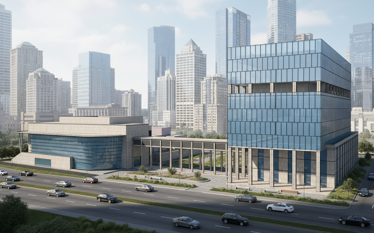
High-quality perspective rendering of a modern office complex, featuring a large auditorium on the left side. Buildings use sleek glass curtain walls combined with elegant stone cladding. A wide road with realistic cars runs in the foreground, while a city skyline with tall contemporary buildings fills the background. Photorealistic, professional architectural visualization style, with natural daylight and sharp details
Oct 4